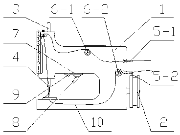
Sewing machine with rotary LED (Light Emitting Diode) lamp

A technology of LED lights and sewing machines, which is applied in the direction of sewing machine components, sewing equipment, lighting device parts, etc., and can solve the problems of high energy consumption and inability to illuminate the light

Inactive Publication Date: 2012-10-03
WUJIANG YIHUALI SILK FASHION
5 Cites 3 Cited by

AI-Extracted Technical Summary

Problems solved by technology

Most of the sewing machines currently in use do not have special lights. Even if they do, they only have an LED ...

Method used

When the preferred embodiment of the present invention works, the required lighting position and the number of lamps are determined by the photosensitive sensor, and then the LED lamp automatically rotates to th...

Abstract

The invention provides a sewing machine with a rotary LED (Light Emitting Diode) lamp, which comprises a sewing machine main body, a belt pulley, a machine needle oscillating rod and a to-be-sewn line, wherein the machine needle oscillating rod is mounted on the upper part of the sewing machine main body; a machine needle is mounted at the bottom of the machine needle oscillating rod; the belt pulley is arranged on the lower part of the sewing machine main body; two lifting pressing cams are arranged on the sewing machine main body; the to-be-sewn line enters from one side of the sewing machine main body, and then successively passes through a first lifting pressing cam, the machine needle oscillating rod, the machine needle, an inner executing mechanism and a second lifting pressing cam, and lastly exits from the sewing machine main body; a lamp holder is arranged on the bottom side of a machine head of the sewing machine main body; and the rotary LED lamp and a photosensitive sensor are mounted on the lamp holder. According to the sewing machine with the rotary LED lamp designed by the invention, the photosensitive sensor on the sewing machine is used for confirming a to-be-illuminated position, and then the LED lamp is automatically rotated to the corresponding position for illuminating.

Application Domain

Point-like light sourceElectric circuit arrangements +3

Technology Topic

EngineeringCam +4

Image

  • Sewing machine with rotary LED (Light Emitting Diode) lamp

Examples

  • Experimental program(1)

Example Embodiment

[0017] The following describes the invention in detail with reference to the drawings and embodiments:
[0018] The invention designs a sewing machine with a rotating LED lamp, which can determine the required lighting position through the light sensor on it, and then the LED lamp automatically rotates to the corresponding position for lighting.
[0019] As an embodiment of the present invention, the present invention provides structural diagrams such as figure 1 A sewing machine with a rotating LED lamp is shown, comprising a sewing machine main body 1, a belt pulley 2, a needle swing lever 3, and a thread to be sewn 10. The needle swing lever 5 is installed on the upper part of the sewing machine main body 1, and the needle swings An organic needle 6 is installed at the bottom of the rod 5, and a belt pulley 4 is provided at the lower part of the sewing machine body 1. The sewing machine body 1 has two lifting cams. The sewing thread 10 enters from the sewing machine body 1, and then passes through the first The lifting cam 8-1 passes through the needle swing lever 5 and the needle 6, and then through the internal actuator 2 and the second lifting cam 8-2 in turn, and finally the thread is discharged from the sewing machine body 1, the sewing machine body 1 head There is a lamp holder 7 on the bottom side. The lamp holder 7 is equipped with a rotating LED lamp 8 and a light sensor 9. The rotating LED lamp has one lamp cap. The patented rotating LED lamp can be equipped with 1-3 lamp caps and one Lamp holder lighting has certain limitations. Setting up one lamp holder has certain limitations but the cost is low. Although multiple lamp holders can be switched on and off as needed, the cost is relatively high, so the number of lamp holders should be three.
[0020] As a preferred embodiment of the present invention, the present invention provides a side view such as figure 1 A sewing machine with a rotating LED lamp is shown, comprising a sewing machine main body 1, a belt pulley 2, a needle swing lever 3, and a thread to be sewn 10. The needle swing lever 5 is installed on the upper part of the sewing machine main body 1, and the needle swings An organic needle 6 is installed at the bottom of the rod 5, a belt pulley 4 is arranged at the lower part of the sewing machine body 1, the sewing machine body 1 has two lifting cams and two guide rods, and the two guide rods are arranged on the side of the sewing machine body 1. , The thread to be sutured 10 enters from the first guide rod 5-1 on the side of the sewing machine body 1, and then passes through the first lifting cam 8-1, and then passes through the needle swing rod 5 and the needle 6, and then sequentially executes internally The mechanism 2 and the second lifting cam 8-2 are finally discharged from the second wire rod 5-2 of the sewing machine main body 1. The sewing machine main body 1 has a lamp holder 7 on the bottom side of the machine head, and a rotating LED is installed on the lamp holder 7 Lamp 8 and light sensor 9. The rotating LED lamp has 3 lamp caps. The rotating LED lamp of this patent can be set with 1-3 lamp caps. There are certain limitations in setting one lamp cap to illuminate, and setting one lamp cap to illuminate has certain limitations but costs It is lower, and it is more expensive to set up multiple lamp holders, although it can be switched on and off as needed, so the number of lamp holders is preferably 3.
[0021] In the preferred embodiment of the present invention, the light sensor determines the required lighting position and the number of lights when working, and then the LED lights automatically rotate to the corresponding position for lighting. Therefore, it is more power-saving and automatic operation, so no special person operation is needed. Affect the operator's illumination, and can illuminate some blind spots.
[0022] The above are only preferred embodiments of the present invention, and are not intended to limit the present invention in any other form. Any modification or equivalent change made according to the technical essence of the present invention still belongs to the scope of protection claimed by the present invention. .

PUM

no PUM

Description & Claims & Application Information

We can also present the details of the Description, Claims and Application information to help users get a comprehensive understanding of the technical details of the patent, such as background art, summary of invention, brief description of drawings, description of embodiments, and other original content. On the other hand, users can also determine the specific scope of protection of the technology through the list of claims; as well as understand the changes in the life cycle of the technology with the presentation of the patent timeline. Login to view more.
Why Eureka
Try Eureka