Lamp combination

A lamp and seat technology, applied in the field of lamp combination, can solve the problem that the lamp cannot be fixed on the hat, etc.

Inactive Publication Date: 2007-06-13
TOPEAK
View PDF0 Cites 0 Cited by
  • Summary
  • Abstract
  • Description
  • Claims
  • Application Information

AI Technical Summary

Problems solved by technology

However, the existing car lamp fixing structure cannot fix the lamp on the hat so as to achieve the purpose that the light can move with the line of sight

Method used


Image

  • Lamp combination
  • Lamp combination
  • Lamp combination

Examples


Embodiment Construction

[0026] Regarding the technology, means and effects used in the present invention, a preferred embodiment is given and described in detail below with drawings, which are for illustration purposes only, and are not limited by this structure in the patent application.

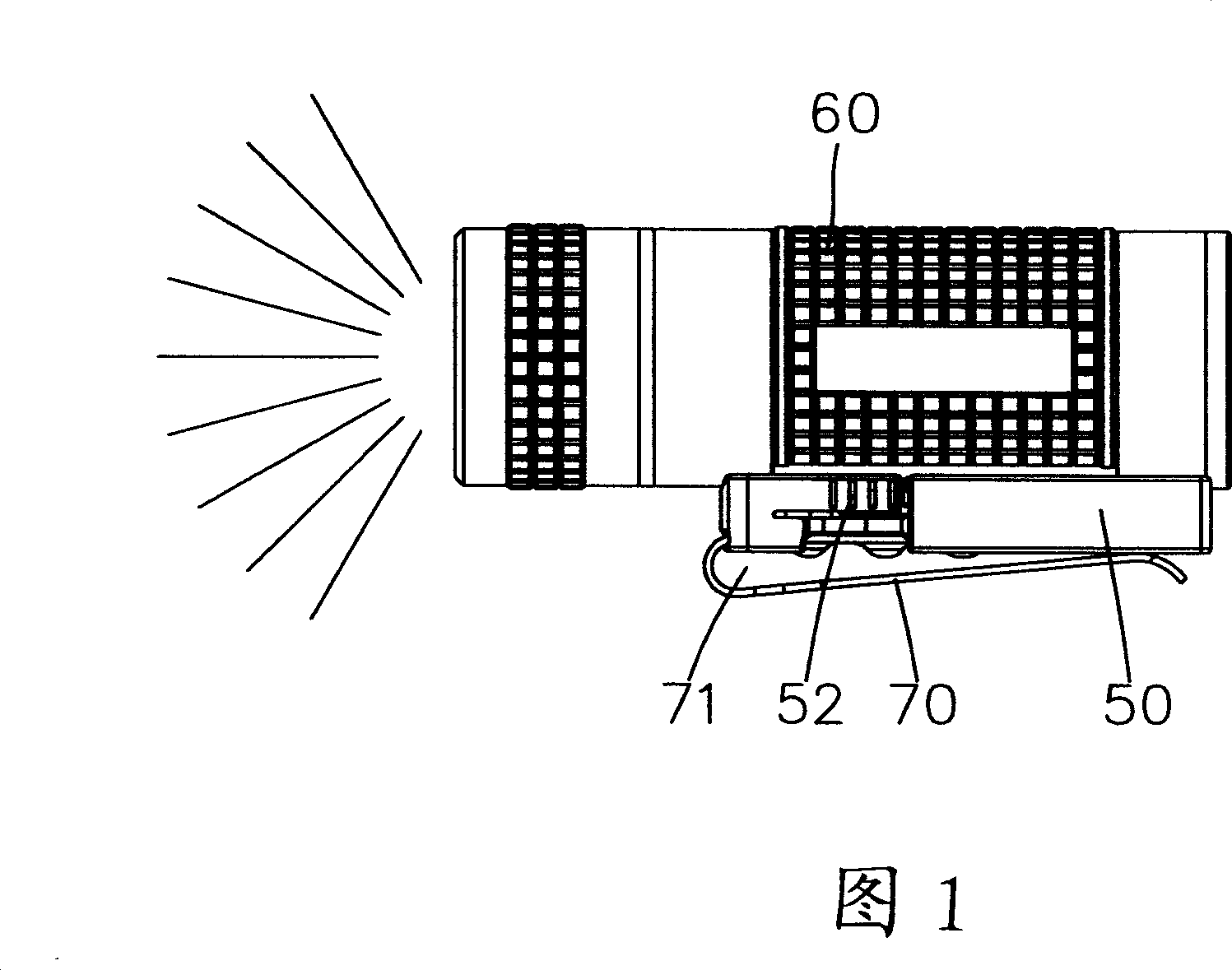
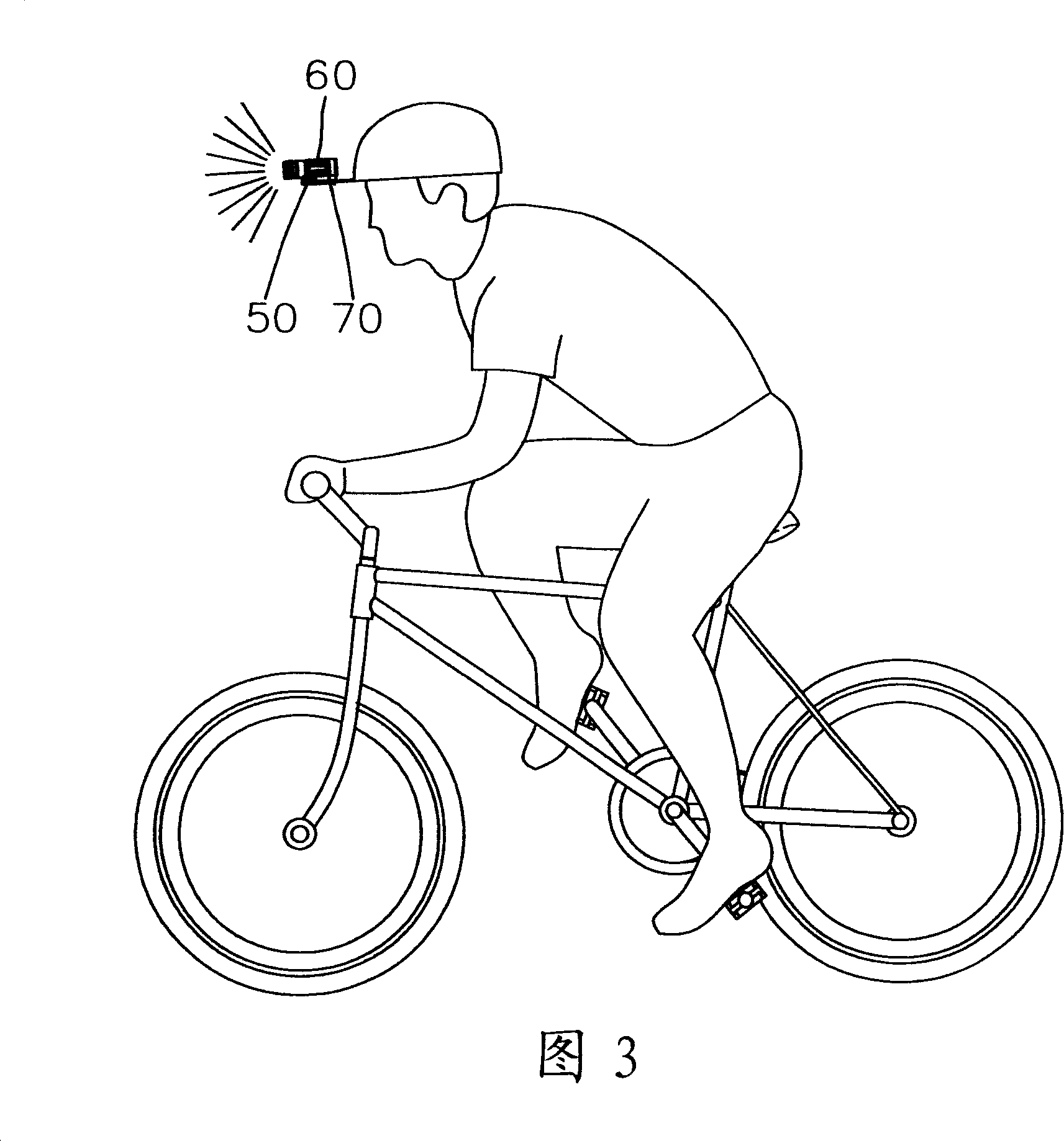
[0027] Please refer to Fig. 1, which is the first embodiment of the present invention. The lamp combination is composed of a base 50 , a lamp 60 and a shrapnel 70 . in:

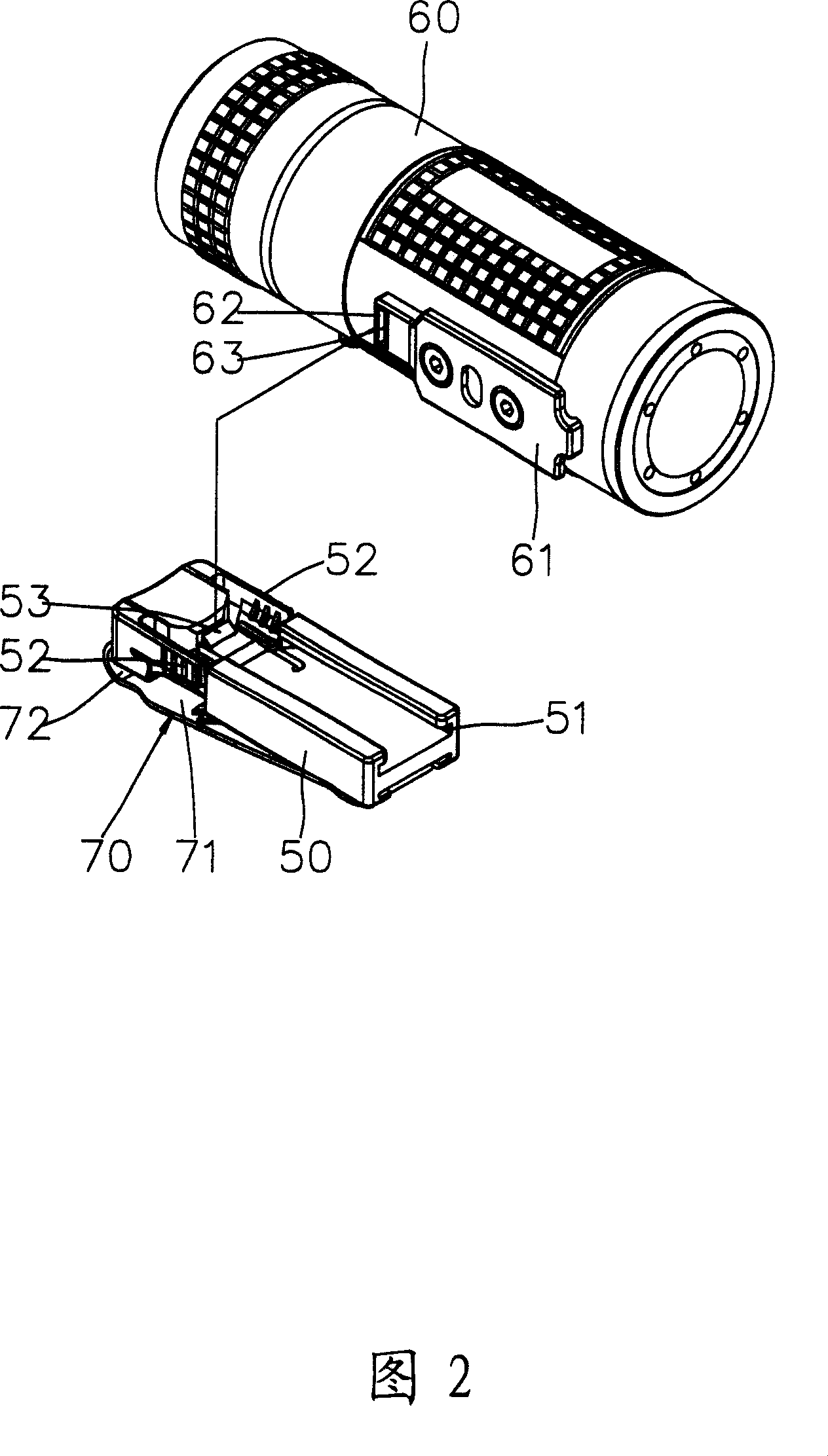
[0028] Please refer to Fig. 2, the base body 50 has a first surface and a second surface, the first surface of the base body 50 is provided with a sliding groove 51, the sliding groove 51 has an open end and a closed end, and the The seat body 50 is respectively provided with a pressing portion 52 on both sides of the closed end of the chute 51 , and the chute 51 is provided with a locking block 53 in the closed end which can be affected by the linkage of the two pressing portions 52 .

[0029] The lamp 60 is provided with a slide rail 61, the ...


PUM


Abstract

The invention supplies a light fitting combination. It includes one base body, one light fitting, and one elastic gripping sheet. It can light the place in sight line, adjust upper and lower illumination angles by adjusting cap edge to light running route for the biker without using both hands to change light fitting illumination place. Even if the light fitting combination separates from the bonder cap, it can combine with other objects, and hang on the waist etc. The invention has the advantages of simple structure, fast assemble, and great utilization and advance performances for the industry.

Description

technical field [0001] The invention relates to a combination of lamps, in particular to a combination of lamps that can provide illumination to the place where the line of sight reaches, and does not need to control the lighting range of the lamp with hands, and allows more space for the hands to be used. Background technique [0002] Please refer to FIG. 7 , which is a conventional lamp fixing structure 10 , which includes a socket 11 , a belt 12 and a locking member 13 . The socket 11 has a first side and a second side, wherein the first side can be detachably combined with the lamp. The belt 12 is arranged on the second side of the seat 11, and the belt 12 is ring-shaped, and the ring size of the belt 12 can be adjusted within a certain range, and the belt 12 can be connected to the bicycle. and the seat 11 carrying the lamp is combined with the belt 12, so that the bicycle driver driving in the dark can also obtain illumination. The locking member 13 can define the st...

Claims


Application Information

Patent Timeline
IPC IPC(8): F21V21/34F21V21/088F21W101/023F21W107/13
Inventor 庄士文
Owner TOPEAK
Why Eureka
Try Eureka