Heat dissipation device for electronic equipment

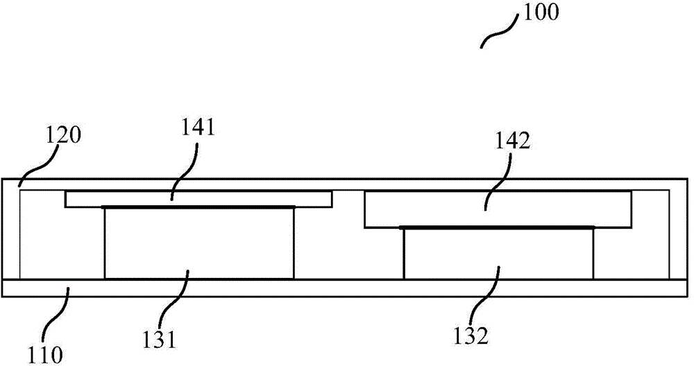
A technology for heat sinks and electronic equipment, applied in the direction of cooling/ventilation/heating transformation, etc., can solve the problems of low heat capacity of the thermally conductive support 120, inability to export heat from heating devices, and prone to local hot spots, etc., so as to improve the user experience and increase the thickness. , the effect of reducing the spacing

Active Publication Date: 2016-02-17
LENOVO (BEIJING) LTD
View PDF9 Cites 17 Cited by
  • Summary
  • Abstract
  • Description
  • Claims
  • Application Information

AI Technical Summary

Problems solved by technology

Although this method can introduce the heat of the heat-generating device to the heat-conducting support 120 to realize local heat dissipation, the thickness of the heat-conducting support 120 in the prior art is generally relatively uniform. Therefore, in order to avoid the highest device on the printed circuit board, the heat-conducting support 120 has to be made very thin, resulting in low heat capacity of the heat conducting bracket 120 itself, and due to the large thermal resistance of the heat conducting bracket 120 for lateral heat transfer, the heat conducting bracket 120 is prone to local hot spots; in addition, for heating devices of different heights, Heat conduction sheets 140 of different thicknesses are required to transfer heat to the bracket, but the heat conduction performance of the heat conduction sheets 140 is far worse than that of the support, and thicker heat conduction sheets 140 cannot fully conduct heat from the heat-generating device

Method used


Image

  • Heat dissipation device for electronic equipment
  • Heat dissipation device for electronic equipment
  • Heat dissipation device for electronic equipment

Examples


Embodiment Construction

[0020] Hereinafter, preferred embodiments of the present invention will be described in detail with reference to the accompanying drawings. Note that, in this specification and the drawings, steps and elements having substantially the same are denoted by the same reference numerals, and repeated explanations of these steps and elements will be omitted.

[0021] Reference throughout this specification to "one embodiment" or "an embodiment" means that a particular feature, structure, or characteristic described in connection with the described embodiment is included in at least one of the described embodiments. Thus, appearances of the phrases "in one embodiment" or "in an embodiment" in the specification are not necessarily all referring to the same embodiment. Furthermore, the particular features, structures or characteristics may be combined in any suitable manner in one or more embodiments.

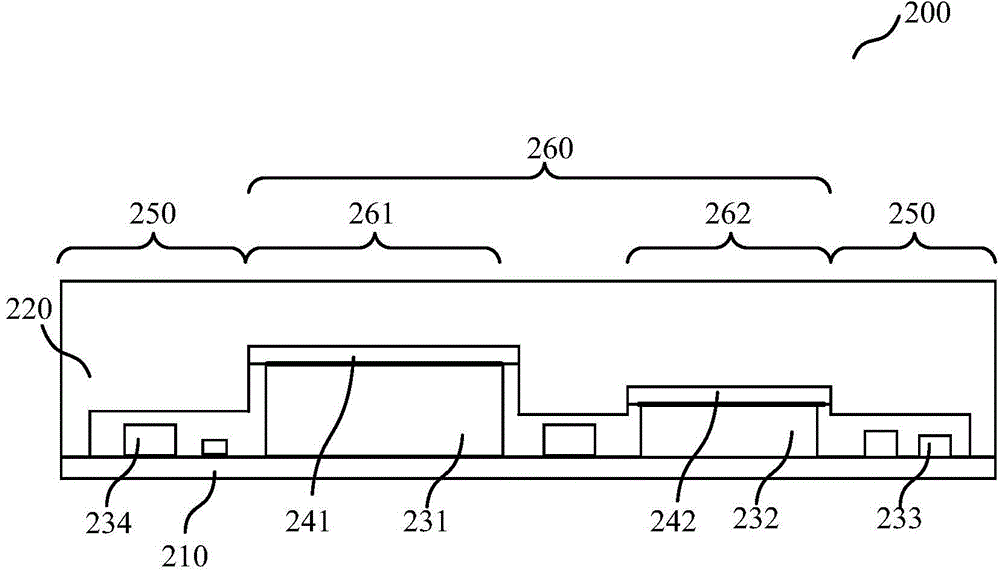
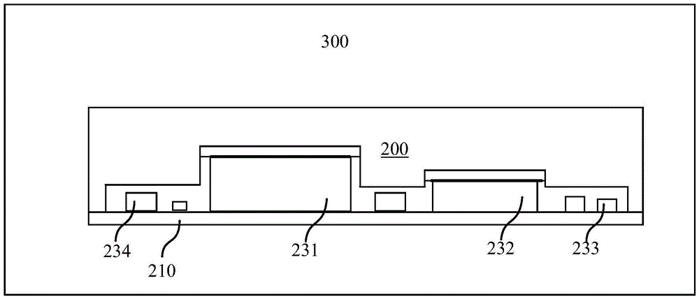
[0022] Below, will refer to figure 2 To describe a heat sink for an electronic d...


PUM


Abstract

The invention provides a heat dissipation device for electronic equipment. The electronic equipment comprises a circuit board, wherein the circuit board is provided with a plurality of electronic devices, and the plurality of electronic devices generate heat in operation. The heat dissipation device comprises a heat conducting bracket which is fixed on the circuit board and covers the plurality of electronic devices, and the heat conducting bracket performs heat conduction with the electronic devices so as to carry out heat dissipation on the electronic devices. The side surface, which is close to the circuit board, of the heat conducting bracket comprises a first region and a second region, wherein the first region corresponds to positions of the electronic devices whose height is not greater than a first threshold on the circuit board; and the second region corresponds to positions of the electronic devices whose height is greater than the first threshold on the circuit board, and the heat conducting bracket is sunk inwards so as to form a plurality of grooves. The heat dissipation device provided by the invention can enable heat to be transferred to the metal bracket from heat generating elements quickly and more effectively, thereby improving the heat dissipation effect.

Description

technical field [0001] The present invention relates to a heat dissipation device, and more particularly, to a heat dissipation device for electronic equipment. Background technique [0002] Existing digital products such as mobile phones have more and more cores, faster processing speeds, and more and more heat generation, and the problem of heat dissipation has become increasingly prominent. The thermal design of mobile phones has become a major problem in mobile phone design. Many mobile phone design projects add a lot of heat dissipation materials to deal with the problem of large heat generation, which increases the cost of mobile phone design projects. One of the solutions is to use a thermally conductive bracket with a thermally conductive sheet to conduct the heat of the heating device to the bracket, and rely on the good thermal conductivity of the thermally conductive bracket to make the temperature on the plane of the entire thermally conductive bracket as uniform...

Claims


Application Information

Patent Timeline
Patent Type & Authority Applications(China)
IPC IPC(8): H05K7/20
Inventor 缪江平林峰
Owner LENOVO (BEIJING) LTD
Why Eureka
Try Eureka