
Solid-state fuel cell and related method of manufacture

a fuel cell and solid-state technology, applied in the manufacture of final products, cell components, electrochemical generators, etc., can solve the problems of reduced capability for high-fuel utilization operation, increased diffusion resistance, and general density of anodes, and achieve enhanced fuel utilization during operation, increased flatness during fabrication, and applicability in construction

Inactive Publication Date: 2005-01-06
GENERAL ELECTRIC CO
View PDF11 Cites 6 Cited by
  • Summary
  • Abstract
  • Description
  • Claims
  • Application Information

AI Technical Summary

Benefits of technology

[0011] The present invention uses existing materials and compositions for anode-supported SOFC's and only slightly modifies the fabrication process so as to provide increased flatness during fabrication, as well as enhanced fuel utilization during operation. It will be understood, however, that the invention is equally applicable to cathodes in cathode-supported SOFC's and may also have applicability in the construction of anodes and cathodes in proton exchange membrane fuel cells (PEM) that use fluorocarbon ion exchange with a polymeric membrane as the electrolyte.

Problems solved by technology

Persistent problems relating to SOFC anode design is the need to insure flatness of the component interface surfaces during fabrication as well as efficiency of fuel utilization during operation.
Secondly, anodes are generally more dense in anode-supported SOFC's since they are fired along with electrolytes at high temperatures required to densify the electrolytes.
Higher density anodes lead to more diffusion resistance and therefore reduced capability for high-fuel utilization operation.
Added poreformers, however, lead to problems in fabrication such as increased stiffness and brittleness in tape calendaring or tape casting operations which, in turn, makes lamination with the electrolyte layer difficult.
This can lead to increased and often uneven heat generation, and decreased yield from slowing down the firing cycle, which adds significantly to cost.
This approach is usually accompanied by inadequate densification of the electrolyte, however, leading to leaks through the electrolyte and lower performance of the cell, or even outright cell failure.
This approach, however, leads to decreased strength of the anode, increased warpage and lower yield.

Method used


Image

  • Solid-state fuel cell and related method of manufacture
  • Solid-state fuel cell and related method of manufacture
  • Solid-state fuel cell and related method of manufacture

Examples


Embodiment Construction

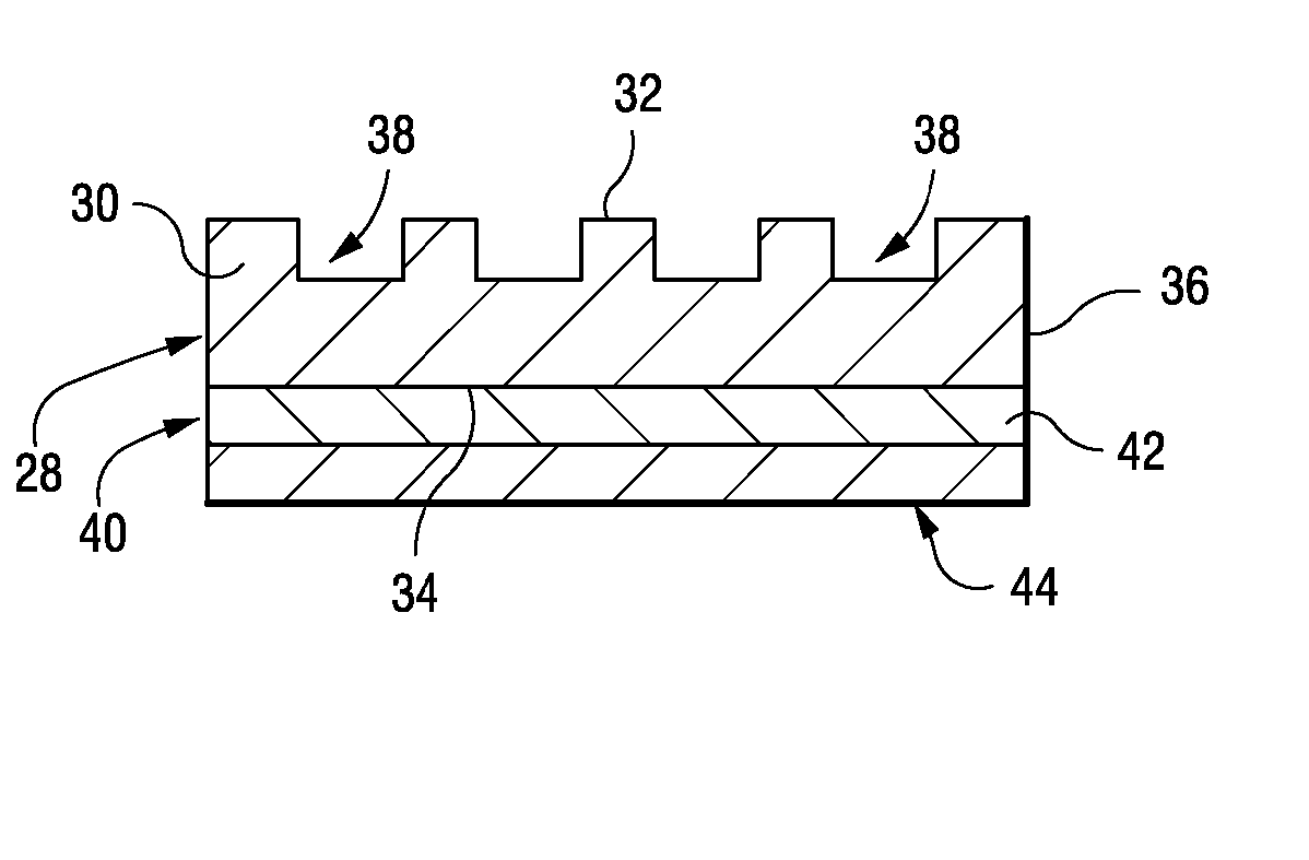
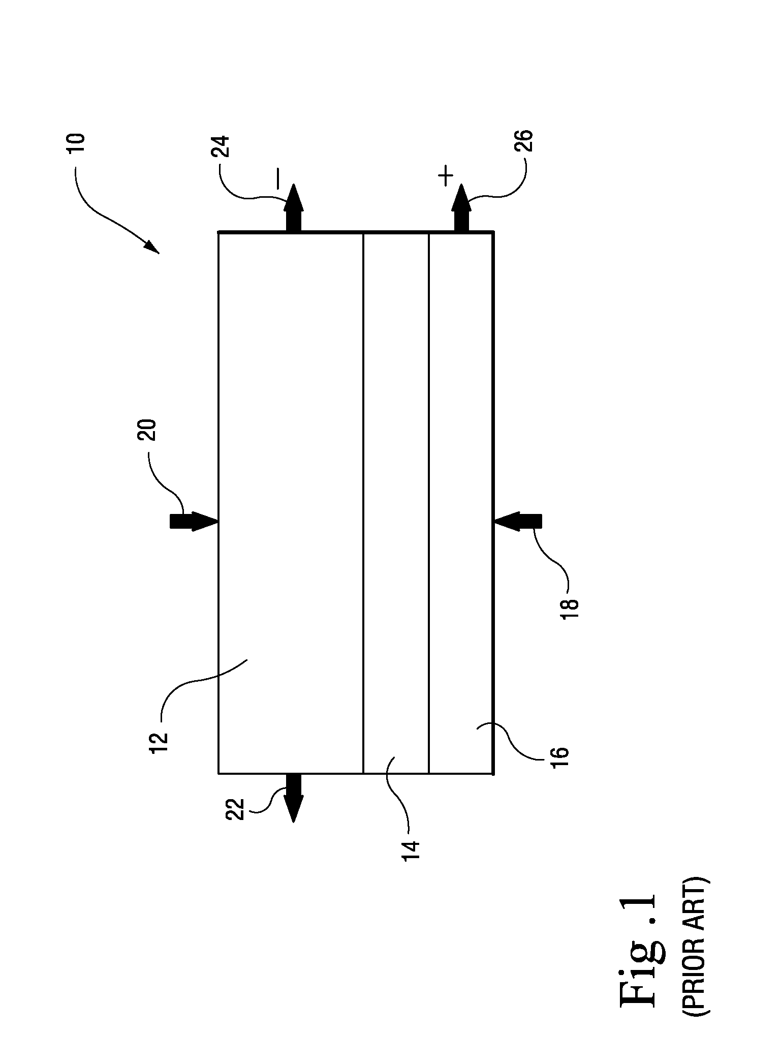
[0021] With reference to FIG. 1, a conventional anode-supported SOFC is shown schematically at 10 and includes an anode 12, electrolyte 14 and cathode 16. The anode 12 is significantly thicker than both the cathode and electrode in the anode-supported type SOFC. In a typical example, the cathode 16 and electrolyte 14 may have thicknesses of about 0.01 to 0.10 mm while the anode 12 may have a thickness of about 0.3 to 2 mm.

[0022] The anode 10 is a ceramic material, e.g., a nickel / zirconium oxide, and the cathode is also a ceramic material, e.g., lanthanum manganite. Both the anode 12 and cathode 16 are relatively porous, allowing gases to pass through for interaction with the electrolyte 14. The electrolyte may comprise a mixture of yttrium oxide and zirconium oxide. It will be appreciated, however, that other suitable compositions may be utilized in connection with this invention.

[0023] In an SOFC, oxygen is added via the cathode 16 as indicated by arrow 18; hydrogen and carbon mo...


PUM

PropertyMeasurementUnit
thicknessaaaaaaaaaa
depthaaaaaaaaaa
thicknessaaaaaaaaaa

Abstract

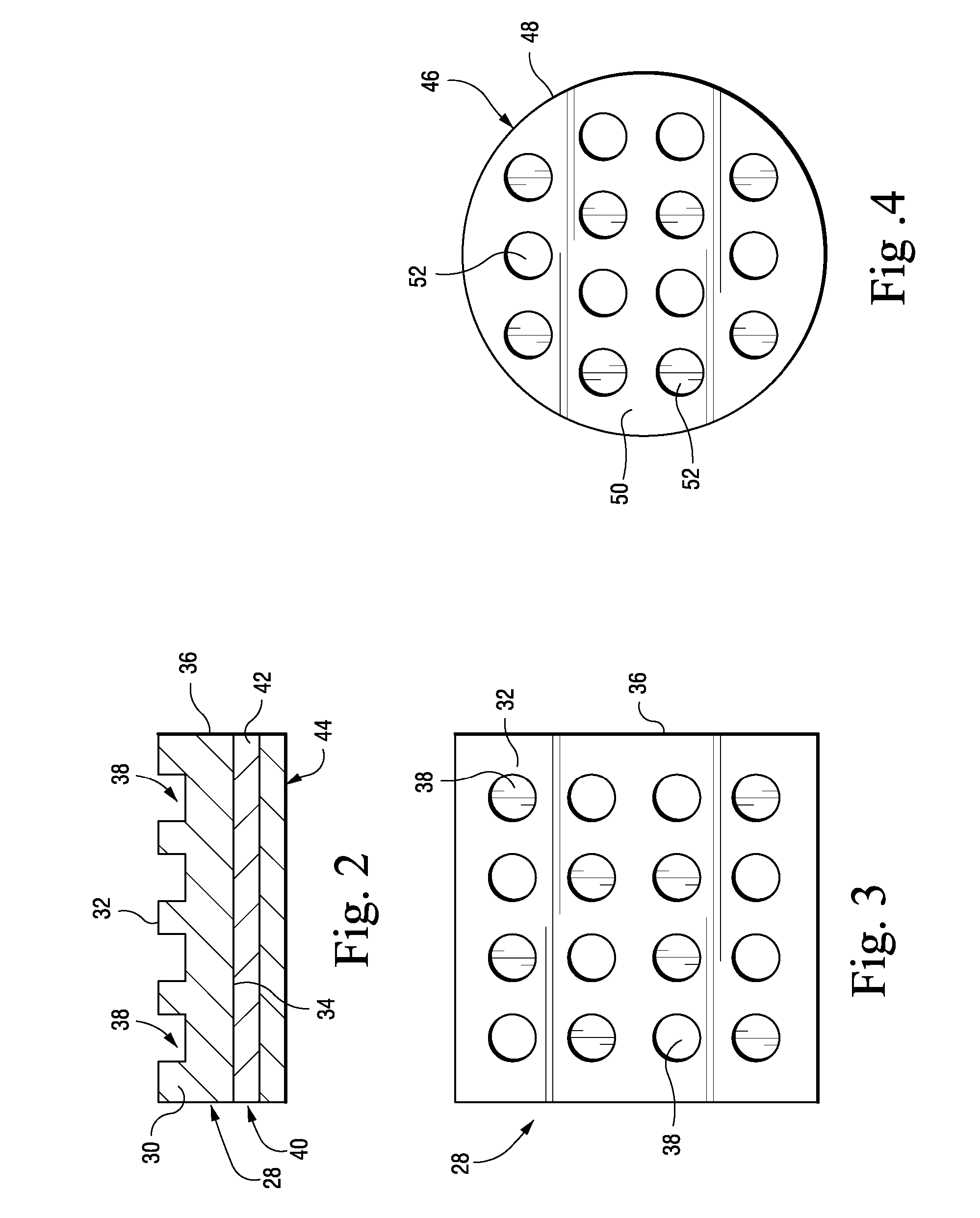
An electrode for a solid-state fuel cell includes a tape having opposite sides joined by a peripheral edge, one of the opposite faces having a plurality of surface depressions therein extending partially through the tape.

Description

BACKGROUND OF INVENTION [0001] The invention relates generally to solid-state fuel electrodes, and more specifically, to an anode configuration for a solid oxide fuel cell (SOFC). [0002] A fuel cell is an electrochemical device in which a hydrogen or a hydrocarbon fuel is electrochemically reacted with air or oxygen to produce electricity, heat and water. A fuel cell typically includes an anode (the fuel electrode) and a cathode (the oxidant electrode). The anode and cathode are made of porous materials that allow gases to move through them. In a solid oxide fuel cell (SOFC), a hard ceramic electrolyte separates the anode from the cathode. [0003] SOFC's typically operate at temperatures as high as 1000° C. Oxygen ions are formed at the oxidant electrode (the cathode), and when the hydrogen or other hydrocarbon fuel is passed over the fuel electrode (the anode), oxygen ions migrate through the hard ceramic electrolyte to oxidize the fuel, transforming the hydrogen to water and carbon...

Claims


Application Information

Patent Timeline
Patent Type & Authority Applications(United States)
IPC IPC(8): H01M4/86H01M4/88H01M8/12
CPCH01M4/8621H01M4/8885H01M8/1213Y02E60/525H01M2004/8684Y02E60/521H01M8/1226Y02P70/50Y02E60/50
Inventor DOSHI, RAJIV
Owner GENERAL ELECTRIC CO
Learn More