Energy-saving lamp

A technology for lamps and lighting lamps, which is applied to cleaning methods and utensils, cleaning methods using tools, lighting and heating equipment, etc. Adjust and aggravate the greenhouse effect incandescent lamps, etc., to achieve the effect of convenient brightness, increased contact area, and improved endurance

Inactive Publication Date: 2021-06-08
绍兴市载沣智能科技有限公司
View PDF1 Cites 0 Cited by
  • Summary
  • Abstract
  • Description
  • Claims
  • Application Information

AI Technical Summary

Problems solved by technology

[0002] At present, reducing energy consumption, saving energy, and paying attention to environmental protection are the main trends in the world today. Incandescent lamps with high energy consumption and aggravating the greenhouse effect are becoming less and less popular. They are used in public places and residential areas of schools, institutions, factories and mines In public corridors, the phenomenon of ever-burning lights is very common, which causes a great waste of energy
[0003] According to an energy-saving LED lamp disclosed in Chinese Patent No. CN108443769B, the irradiation angle of the LED lamp can be adjusted by tilting the motor, and the correspondence between the light distribution mirror and the corresponding LED lamp can be adjusted by rotating the adjusting gear to meet different irradiation requirements. , but the long-term use of the surface absorbs dust, affecting the use
[0004] According to Chinese Patent No. CN108443769B, an energy-saving LED lamp is used to solve the problem that the position between the light distribution mirror and the corresponding LED lamp cannot be adjusted, and cannot be adjusted according to needs, thereby affecting its use.
According to an energy-saving LED lamp disclosed in Chinese Patent No. CN108443769B, the irradiation angle of the LED lamp can be adjusted by tilting the motor, and the correspondence between the light distribution mirror and the corresponding LED lamp can be adjusted by rotating the adjusting gear to meet different irradiation requirements. , but the long-term use of the surface absorbs dust, which affects the use and the brightness of the lamp is weakened
[0005] To sum up, the long-term use of the surface absorbs dust, which affects the use and the brightness of the lamp is weakened

Method used


Image

  • Energy-saving lamp
  • Energy-saving lamp
  • Energy-saving lamp

Examples


Embodiment 1

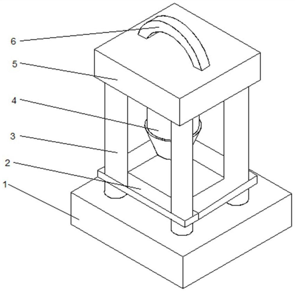
[0032] Such as Figure 1-2 , a technical solution proposed by the present invention: an energy-saving lamp, including a base 1, the top of the base 1 is fixedly connected with a pillar 3 on both sides, the bottom of the pillar 3 is fixedly connected with a fixing frame 2, and the top of the pillar 3 A fixing device 5 is provided, a handle 6 is fixedly connected to the middle position of the top of the fixing device 5 , and an illuminating lamp 4 is arranged at the middle position of the bottom of the fixing device 5 .

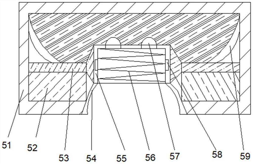
[0033]Wherein, the fixing device 5 includes a casing 51, the bottom of the casing 51 is provided with an installation opening 54, the bottom of the inner cavity of the casing 51 is located on both sides of the installation opening 54, and a lifting mechanism 52 is arranged, and the inner walls of both sides of the casing 51 are located on the top of the lifting mechanism 52 Fixedly connected with a fixed rod 53, the middle position of the top of the fixed rod 5...

Embodiment 2

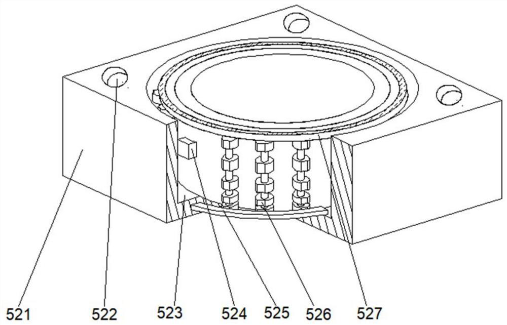
[0036] Such as Figure 1-3 As shown, on the basis of Embodiment 1, the present invention provides a technical solution: the lifting mechanism 52 includes a lifting box 521, and a positioning groove 523 is opened in the middle of the top of the lifting box 521, and the top of the lifting box 521 is located at the top of the positioning groove 523. Positioning holes 522 are provided on both sides, connecting rods 524 are fixedly connected to the middle of the inner walls of both sides of the positioning groove 523, fixed plates 525 are fixedly connected to both sides of the inner cavity bottom of the positioning groove 523, and the top of the fixed plate 525 is provided with an expansion joint. Part 526, the top of the expansion part 526 is fixedly connected with a dust removal mechanism 527.

[0037] When in use, the lighting lamp 4 contacts the energized groove 57 after being fixed, and the lamp enters the inner cover 55 through the installation port 54 to rotate, and is fixed...

Embodiment 3

[0039] Such as Figure 1-5 As shown, on the basis of Embodiment 1 and Embodiment 2, the present invention provides a technical solution: the dust removal mechanism 527 includes a cleaning shell 5274, and both sides of the bottom of the cleaning shell 5274 are fixedly connected with a linkage frame 5273, and the linkage frame 5273 is away from The position of the cleaning shell 5274 is provided with a linkage ring 5278, the top of the back of the cleaning shell 5274 is provided with an adjustment port 5276, the top of the back of the cleaning shell 5274 is located on both sides of the adjustment port 5276, and a fixing mechanism 5277 is provided. A moving block 5271 is provided at the position, and the side of the moving block 5271 far away from the adjustment port 5276 is fixedly connected with an engaging block 5275 , and the end of the engaging block 5275 far away from the moving block 5271 is fixedly connected with a dust removal ring 5272 .

[0040] Among them, the fixing ...


PUM


Abstract

The invention discloses an energy-saving lamp which comprises a base, supporting columns are fixedly connected to the two sides of the top of the base, a fixing frame is fixedly connected to the bottoms of the supporting columns, a fixing device is arranged at the tops of the supporting columns, and a handle is fixedly connected to the middle of the top of the fixing device. And an illuminating lamp is arranged in the middle of the bottom of the fixing device. The invention relates to the technical field of energy-saving lamps. According to the energy-saving lamp, the supporting column, the fixing device and the handle are arranged, dust can be cleaned through dust removal inside the fixing device, so that dust adsorbed on the surface after long-time use is convenient to remove, the brightness degree of the lamp is convenient to protect, the supporting column can be effectively fixed, meanwhile, the lamp is convenient to replace, place and take, the waste of resources can be effectively reduced, the moving direction can be better controlled, the dust removal strength is relieved, and the situation that the lamp is broken due to too large strength is prevented.

Description

technical field [0001] The invention relates to the technical field of energy-saving lamps, in particular to an energy-saving lamp. Background technique [0002] At present, reducing energy consumption, saving energy, and paying attention to environmental protection are the main trends in the world today. Incandescent lamps with high energy consumption and aggravating the greenhouse effect are becoming less and less popular. They are used in public places and residential areas of schools, institutions, factories and mines The phenomenon of ever-burning lights is very common in public corridors, which causes a great waste of energy. [0003] According to an energy-saving LED lamp disclosed in Chinese Patent No. CN108443769B, the irradiation angle of the LED lamp can be adjusted by tilting the motor, and the correspondence between the light distribution mirror and the corresponding LED lamp can be adjusted by rotating the adjusting gear to meet different irradiation requiremen...

Claims


Application Information

Patent Timeline
Patent Type & Authority Applications(China)
IPC IPC(8): F21S6/00F21V21/40B08B1/00F21V17/12
CPCB08B1/002F21S6/00F21V17/12F21V21/40
Inventor 曹敏
Owner 绍兴市载沣智能科技有限公司
Why Eureka
Try Eureka