Inserting-type emergency cut-off valve for liquefied natural gas cylinder

A liquefied natural gas, cartridge technology, applied in valve details, safety valves, balance valves, etc., can solve the problems of cumbersome assembly, maintenance, failure of the restrictor valve, unsuitable system integration, etc., to achieve low installation and maintenance costs, Improve energy efficiency, compact and reasonable structure

Inactive Publication Date: 2012-10-03
江南工业集团有限公司
View PDF7 Cites 0 Cited by
  • Summary
  • Abstract
  • Description
  • Claims
  • Application Information

AI Technical Summary

Problems solved by technology

This connection and function method has defects such as cumbersome assembly and maintenance, and is not suitable for system integration, especially at the moment when the stop valve is opened and starts to use liquid, because there is a pressure difference between the inside of the gas cylinder and the external vaporizer, the vertical tube inside the restrictor valve Under the action of the instantaneous impact force formed by the pressure difference, the steel ball in the road will quickly move to the horizontal pipeline, block the horizontal pipeline, close the valve, and prevent the liquid natural gas from entering the vaporizer
At present, some flow limiting valve manufacturers simply cancel the flow limiting steel ball, which makes the flow limiting valve lose its due function and leaves a safety hazard at the same time.

Method used


Image

  • Inserting-type emergency cut-off valve for liquefied natural gas cylinder
  • Inserting-type emergency cut-off valve for liquefied natural gas cylinder
  • Inserting-type emergency cut-off valve for liquefied natural gas cylinder

Examples


Embodiment Construction

[0020] The preferred embodiments of the present invention will be further described below in conjunction with the accompanying drawings.

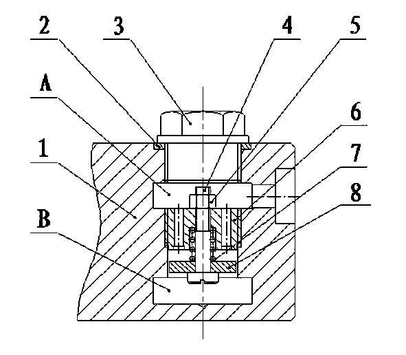
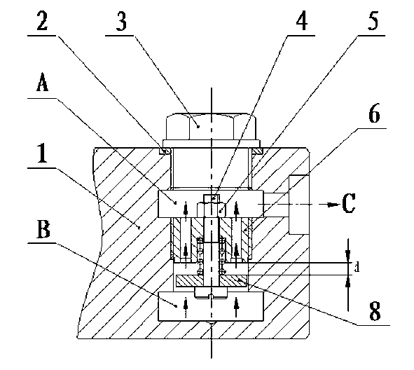
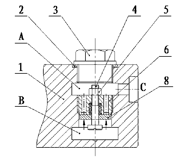
[0021] Referring to the accompanying drawings, a plug-in emergency shut-off valve for liquefied natural gas cylinders includes a distribution head 1, a seal 2, a plug gland 3, an adjusting nut 4, a bolt 5, a screw seat 6, a spring 7, and a valve plate 8 .

[0022] The screw seat 6 is designed as a threaded cylinder for the outer cylindrical surface, and the axial design of the screw seat 6 has six through holes 9 that are equally divided into 60° and a central through hole 10 that is designed with a step stop in the middle of an inner wall.

[0023] The valve plate 8 and the spring 7 are sequentially set into the bolt 5 from the front end of the bolt 5, and the bolt 5 with the valve plate 8 and the spring 7 is installed into the center through hole 10 of the screw seat 6 from the lower end of the screw seat 6, and one end of the spring 7 is...


PUM


Abstract

The invention relates to an inserting-type emergency cut-off valve for a liquefied natural gas cylinder. The inserting-type emergency cut-off valve has the main technical characteristic of comprising a distributing head, a seal element, a plug screw pressing cover, an adjusting nut, a bolt, a screw seat, a spring and a valve sheet, wherein the screw seat is an externally-threaded cylinder with a cylindrical surface, six through holes mutually forming 60-degree angles mutually and a center through hole are formed on the screw seat, and a step limiting opening is formed at the middle part of the inner wall of the center through hole. The bolt is sleeved with the valve sheet and the spring; the external diameter of the valve sheet is less than the diameter of the inner cavity of the distributing head; the valve sheet can overcome the reacting force of the spring under the action of external force to make an upward motion along the bolt; the separation distance (d) between the upper surface of the valve sheet and the lower surface of the screw seat ranges from 2.5 mm to 4 mm; the external thread of the screw seat is installed in the inner cavity of the distributing head so as to divide the inner cavity into an A cavity and a B cavity; and a C thread connecting opening formed on the side end surface of the distributing head is communicated with the A cavity. The inserting-type emergency cut-off valve has the advantages of compact and reasonable structure, small abrasion, long service life, high reliability, good safety performance, convenience in detection and maintenance, and the like.

Description

technical field [0001] The invention relates to a plug-in type emergency shut-off valve for liquefied natural gas cylinders, which is especially suitable for gently balancing the internal and external pressure difference at the moment of liquid consumption when the liquefied natural gas shut-off valve is opened, and automatically blocking the large amount of liquefied natural gas when the liquid pipeline for liquefied natural gas bursts unexpectedly. Leaked. Background technique [0002] Liquefied natural gas (LNG) is a low-temperature liquefied natural gas. Its storage, transportation and use must use special liquefied natural gas cylinders or tanks. Among them, the flow limiting valve plays a role of safety protection in the gas supply system. In the background technology, the restrictor valves used in the domestic liquefied natural gas field are vertically installed on the external pipeline of the distribution head, that is, a stainless steel pipe with an internal thread ...

Claims


Application Information

Patent Timeline
Patent Type & Authority Applications(China)
IPC IPC(8): F16K17/00F16K27/00
Inventor 王湘江李德侔李崇华杨鹏
Owner 江南工业集团有限公司
Why Eureka
Try Eureka