Automatic ventilation method for anechoic chamber

An anechoic chamber, automatic technology, applied in the direction of space heating and ventilation, heating and ventilation control systems, heating and ventilation safety systems, etc., can solve problems such as internal noise impact

Active Publication Date: 2012-10-03
亦宸五金(浙江)股份有限公司
View PDF11 Cites 1 Cited by
  • Summary
  • Abstract
  • Description
  • Claims
  • Application Information

AI Technical Summary

Problems solved by technology

[0003] The existing ventilation system will design a sound-absorbing duct to suppress the impact of the fan and external noise on the interior of the room, but for the test environment with relatively high background noise requirements, the impact on its internal noise is still very large

Method used


Image

  • Automatic ventilation method for anechoic chamber

Examples


Embodiment Construction

[0016] The technical solution of the present invention will be described in further non-limiting detail below in combination with preferred embodiments and accompanying drawings.

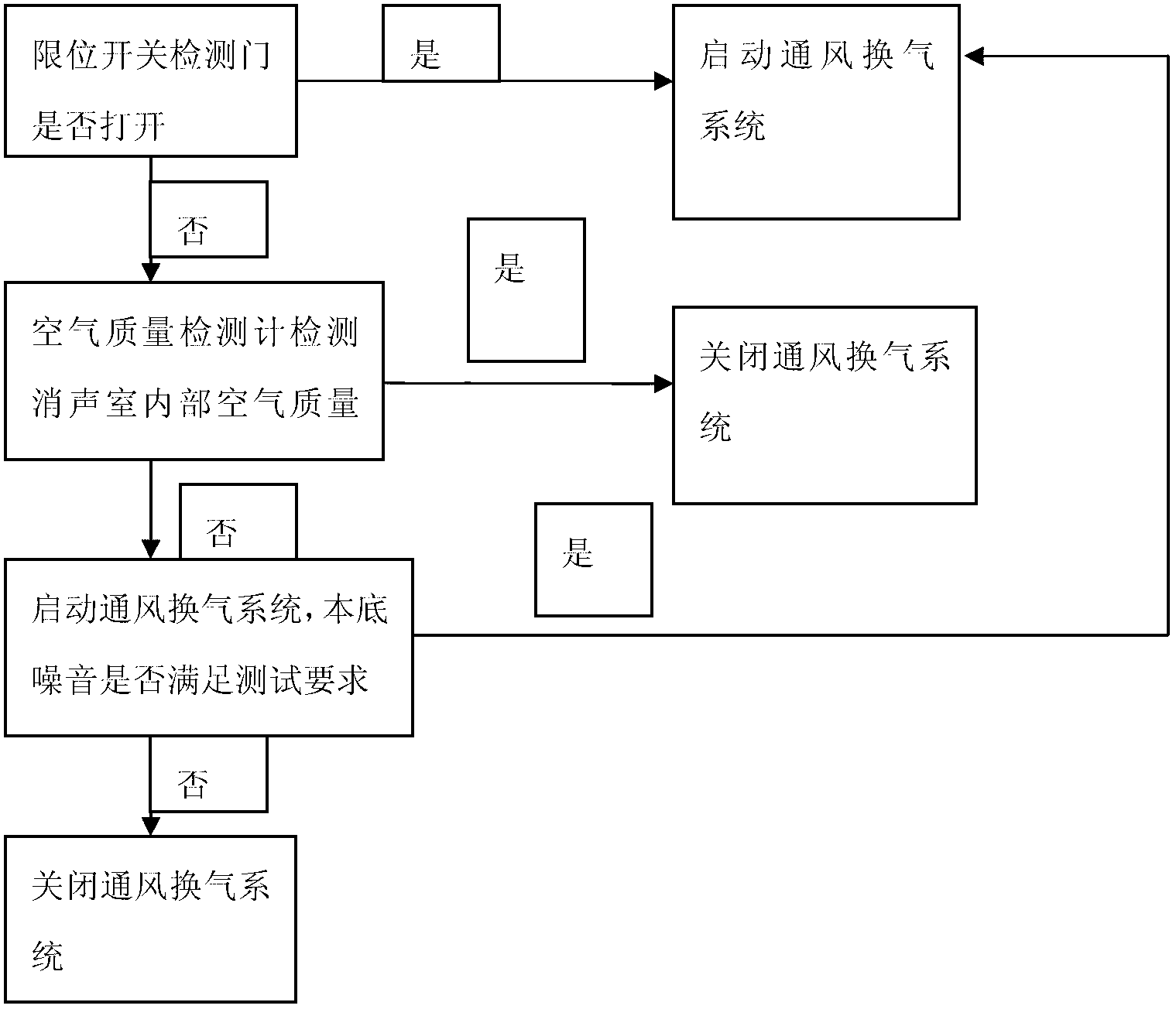
[0017] refer to figure 1 , an automatic ventilation method for an anechoic chamber, comprising the steps of: providing a limit switch (not shown), for detecting the opening and closing state of the entrance and exit door of the anechoic chamber; providing an air quality detector (not shown), Used to detect the air quality inside the anechoic chamber; and provide a ventilation system (not shown), and selectively start or close the Ventilation system.

[0018] Specifically, the above-mentioned ventilation system and air quality detector are common in the prior art, and will not be repeated here. The limit switch is installed on the entrance and exit door (not shown) of the anechoic chamber. If the limit switch detects that the entrance and exit door of the anechoic chamber is open, the ventilation ...


PUM


Abstract

The invention discloses an automatic ventilation method for an anechoic chamber. The method comprises the following steps of: providing a limit switch for detecting the opening and closing state of an access door of the anechoic chamber; providing an air quality detector for detecting the air quality in the anechoic chamber; and providing a ventilation system, and selectively opening or closing the ventilation system according to the opening and closing state of the access door and the air quality in the anechoic chamber. Therefore, the method can meet the requirement for ventilation of the anechoic chamber, and can also well meet the basic requirement of acoustic test.

Description

technical field [0001] The invention relates to an automatic ventilation method for an anechoic chamber. Background technique [0002] In the acoustic test environment, in order to ensure a good sound insulation effect, whether it is an anechoic room or a silent room, it is generally required to be completely sealed. However, sometimes the operator needs to enter the anechoic room or silent room for equipment debugging, so it is required to have a good air environment inside the room, so it is generally necessary to design and establish a ventilation system. [0003] The existing ventilation system will design a sound-absorbing duct to suppress the impact of the fan and external noise on the interior of the room. However, for the test environment with relatively high background noise requirements, the impact on the internal noise is still very large. Contents of the invention [0004] The object of the present invention is to provide an improved method for automatic venti...

Claims


Application Information

Patent Timeline
Patent Type & Authority Applications(China)
IPC IPC(8): F24F11/00F24F13/24
CPCY02B30/78Y02B30/70
Inventor 付迅
Owner 亦宸五金(浙江)股份有限公司
Why Eureka
Try Eureka