
Coal mine inclined shaft standby explosion door device

A technology for explosion-proof doors and inclined shafts, which is applied to mining equipment, mining equipment, sealing devices, etc., and can solve the problems of flushing away from the wellhead, casualties of underground personnel, and inability to isolate underground airflow.

Pending Publication Date: 2021-04-06
CHONGQING UNIV
View PDF6 Cites 1 Cited by
  • Summary
  • Abstract
  • Description
  • Claims
  • Application Information

AI Technical Summary

Problems solved by technology

However, at present, some coal mines that have been used for a long time still use the old-fashioned coal mine inclined shaft explosion-proof doors. The old-fashioned coal mine inclined shaft explosion-proof doors have certain disadvantages due to their structure. The impact caused by being washed away from the wellhead or severely deformed, so that the explosion-proof door cannot be closed and reset in time after opening, so that the downhole air flow cannot be isolated from the ground atmosphere, resulting in a short circuit of the air flow, resulting in a large amount of high-temperature, toxic and harmful gases produced by the gas explosion. discharge, causing a large number of underground casualties
In addition, due to the needs of underground rescue work, it may be necessary to reverse the wind in the mine. At this time, because the explosion-proof door leaf cannot be closed in time, it will also cause a short circuit of the air flow, so that the direction of the air flow cannot be changed within the specified time, thus affecting the underground rescue work. Big Downhole Casualties

Method used


Image

  • Coal mine inclined shaft standby explosion door device
  • Coal mine inclined shaft standby explosion door device
  • Coal mine inclined shaft standby explosion door device

Examples


Embodiment Construction

[0025] The present invention will be described in detail below in conjunction with the accompanying drawings.

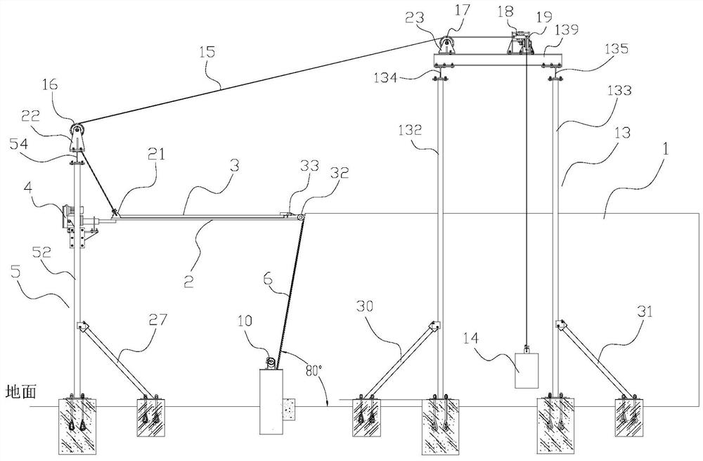
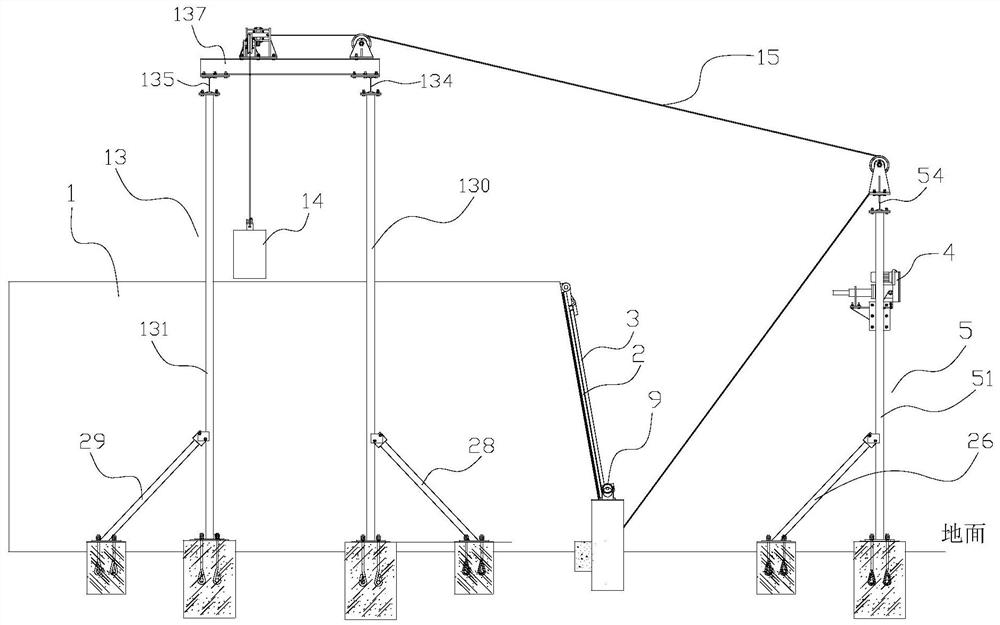
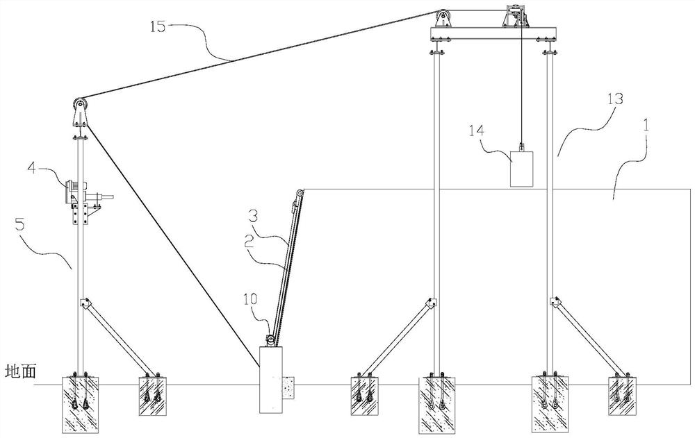
[0026] Such as Figure 1 to Figure 10 The shown backup explosion-proof door device for an inclined shaft in a coal mine includes a concrete box 1, a door leaf 2, a window leaf 3, two first electric push rod mechanisms 4, a first bracket 5, a second electric push rod mechanism 9, and a third electric push rod mechanism. Electric push rod mechanism 10, first locking plate 11, second locking plate 12, second support 13, electric control system and two sets of counterweight systems. The electric control system (not shown in the figure) is used to provide power for two first electric push rod mechanisms 4, one second electric push rod mechanism 9, and one third electric push rod mechanism 10, and at the same time receive the remote control command, and according to the remote control command, control the extension and retraction of the push rods of the two first electric...


PUM


Abstract

The invention discloses a coal mine inclined shaft standby explosion door device. The standby explosion door device comprises a concrete box body, a door leaf, a window sash, first electric push rod mechanisms and a first support, wherein the front end of the concrete box body is provided with an outlet capable of directly facing an inclined shaft explosion door, a rigid door frame is formed on the periphery of the outlet, the upper side edge of the door leaf is hinged to the upper side edge of the rigid door frame, the door leaf can cover the front portion of the outlet and obtain supporting force through the rigid door frame, a pressure relief window is formed in the door leaf, the upper side edge of the window sash is hinged to the upper edge of the pressure relief window, the window sash covers the front portion of the pressure relief window and obtains supporting force through the edge of the pressure relief window, the first electric push rod mechanism is installed on the first support, when push rods of the first electric push rod mechanisms extend backwards, the door leaf can be supported, and the outlet is completely opened. When the standby explosion door device is uses, the device covers an inclined shaft body protruding out of the ground and the inclined shaft explosion door, the standby explosion door is used for quickly resetting to close a channel after primary explosion occurs underground, and normal pressure relief and resetting can be realized when multiple explosions occur underground.

Description

technical field [0001] The invention belongs to the technical field of coal mine safety protection, and in particular relates to a backup explosion-proof door device for an inclined shaft in a coal mine. Background technique [0002] The coal mine inclined shaft explosion-proof door is a special airtight door installed on the wellhead with an inclined shaft body protruding from the ground. Its function is: during normal ventilation, it is used to isolate the downhole airflow from the ground atmosphere, prevent short-circuit of the airflow, and ensure the normal operation of the ventilation system. When a gas or coal dust explosion accident occurs underground, the explosion-proof door is opened by the impact of high-pressure air waves, so that the explosive air flow is directly discharged into the ground atmosphere to relieve pressure and prevent the main ventilator from being impacted by the explosive air flow causing damage. However, at present, some coal mines that have ...

Claims


Application Information

Patent Timeline
IPC IPC(8): E21F17/12E06B5/12E06B3/38E06B7/16E05B47/00E05F1/02E05F5/00
CPCE21F17/12E06B5/12E06B5/125E06B3/38E06B7/16E05B47/0001E05F1/02E05F5/00
Inventor 王亮余明高刘松林喻锦涛杨鑫磊陈结吴斐李林王文乾吴明求
Owner CHONGQING UNIV
Learn More