Ventilating tower wind-power axial flow fan

A technology of axial fans and ventilation towers, which is applied to wind power generation, wind engines, and wind engines at right angles to the wind direction, etc., which can solve the problem of the impossibility of wind turbines intercepting wind energy at a comparable technical level and the low utilization efficiency of wind energy resources, etc. Problems, achieve the effect of reducing operating costs and saving electric energy

Inactive Publication Date: 2008-05-14
CHINA RAILWAY ERYUAN ENG GRP CO LTD
View PDF0 Cites 1 Cited by
  • Summary
  • Abstract
  • Description
  • Claims
  • Application Information

AI Technical Summary

Problems solved by technology

Although the name of this kind of ventilation equipment using natural wind is different, because the main service object is ordinary buildings, the efficiency of intercepting wind energy from the natural environment is limited by the building itself and its environment, and it is impossible to cooperate with wind power generators. Interception of wind energy on a technological level comparable to
Therefore, the utilization efficiency of this type of equipment for wind energy resources is relatively low

Method used


Image

  • Ventilating tower wind-power axial flow fan
  • Ventilating tower wind-power axial flow fan

Examples


Embodiment 1

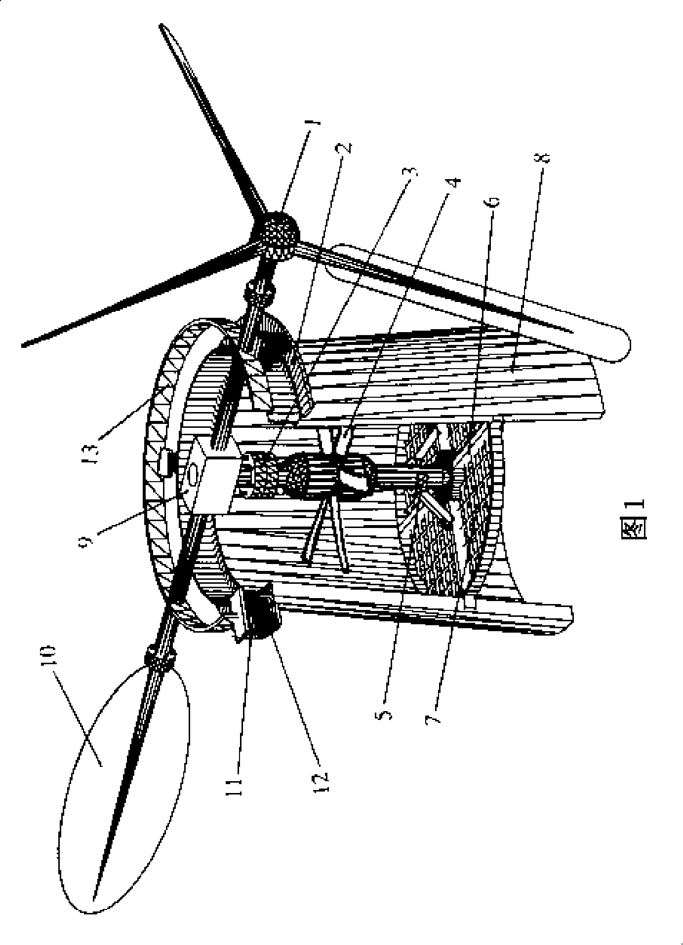
[0020] As shown in FIG. 1 , the wind turbine 1 is a horizontal axis wind turbine. The main shaft of the wind turbine 1 is connected to the input shaft of the gearbox 9, the input shaft and the output shaft of the gearbox 9 are at right angles, the horizontal rotation of the wind turbine is converted into vertical rotation through the gearbox 9, and the axial flow fan is driven by the coupling 3 4 rotates in the ventilation tower 8, and according to the installation direction of the impeller of the axial flow fan 4, the air supply or exhaust is realized from the ventilation tower 8 to the tunnel.

[0021] In order to adapt to the change of the outdoor wind direction, the wind turbine 1 is installed on the movable support 13 on the ventilation tower 8 , and the movable support 13 can rotate along the radial direction of the ventilation tower 8 . And on the movable support 13 at the other end of the axial direction of the main shaft of the wind turbine, a guide fin 10 is installe...

Embodiment 2

[0026] For an environment where the wind direction is stable and does not change much, the guide rail 2, the radial guide wheel 11, the axial guide wheel 12, the movable support 13 and the guide tail 10 can be eliminated, and the main shaft of the wind turbine 1 can be passed through the bearing seat. It is directly installed on the tower body of the ventilation tower 8, and the main shaft of the wind turbine 1 is connected with the main shaft of the axial flow fan through a gear box. The blades of the wind turbine 1 are fixed in a direction corresponding to the wind direction.

Embodiment 3

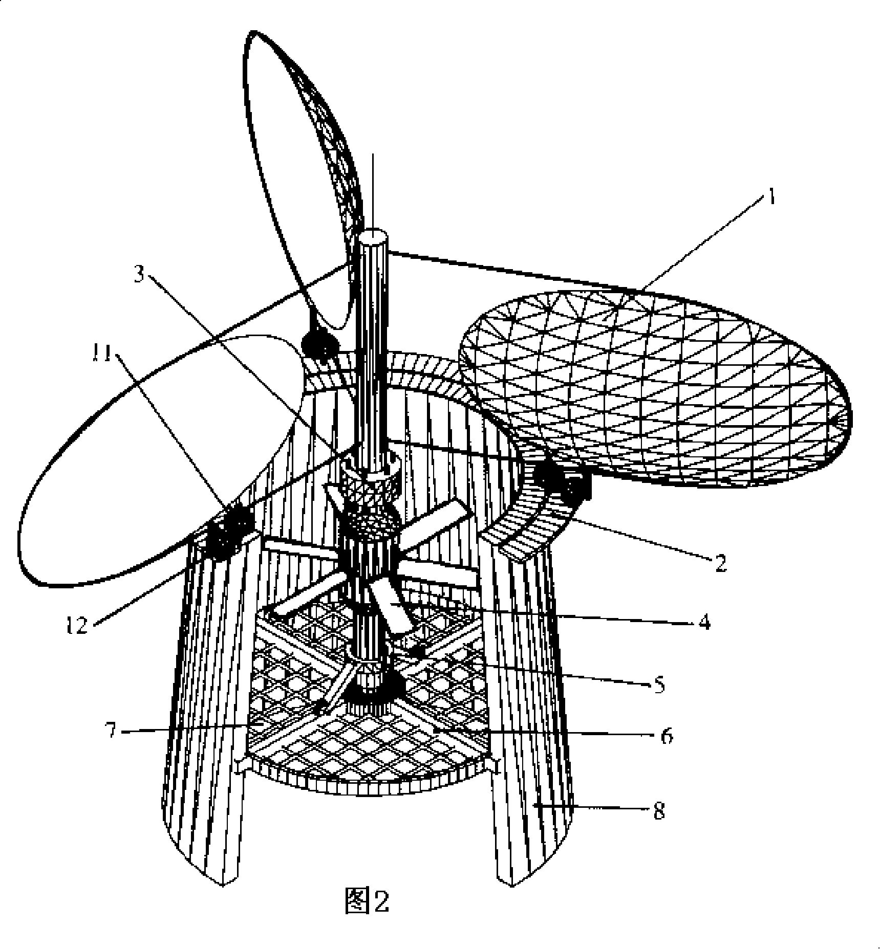
[0028] As shown in FIG. 2 , the wind turbine 1 adopts a vertical axis wind turbine, and is installed on the coaxial line between the mouth of the ventilation tower 8 and the axial flow fan 4 inside the tower. The shaft coupling 3 is directly connected to the axial flow fan 4 to drive the blades of the axial flow fan 4 to rotate. When the wind turbine 1 intercepts the wind energy from the outdoor environment, it directly transmits the axial mechanical motion to the axial flow fan 4 through the coupling 3, and drives the impeller of the axial flow fan 4 to rotate, so that the ventilation tower 8 can discharge air to the outside of the tunnel or inward. air supply.

[0029] In order to make the rotation of the wind turbine 1 stable, a radial positioning wheel 11 and an axial positioning wheel 12 are installed under the blades of each wind turbine 1. The radial positioning wheel 11 is in contact with the outer wall of the ventilation tower 8 for positioning, and the axial position...


PUM


Abstract

The invention discloses a wind axial flow fan, in particular to an exhaust (or air supply) equipment suitable for the ventilation and exhaustion tower in tunnel environments such as road and railway, etc. The technical problem to be solved is that the invention provides the device which utilizes the natural wind energy out of the tunnel to carry out ventilation to the tunnel. The technical proposal adopted by the invention is that the ventilation tower wind axial flow fan is provided with a wind machine out of the ventilation tower of the tunnel; the wind machine is connected with the axial flow fan which is arranged in the ventilation tower by an equipment bracket. The ventilation equipment adopting the invention can convert the outdoor natural wind into axial mechanical motion by the wind machine, which directly drives the axial flow fan on the top of the ventilation tower without going through other energy conversion and accessorially supplements the existing mechanical ventilation driving the fan with power in the tunnel. The equipment sufficiently utilizes renewable energy source, saves the necessary power required by tunnel ventilation, and effectively reduces the operation cost of the tunnel.

Description

technical field [0001] The invention relates to the application of a wind energy axial flow fan, and is especially suitable for the air exhaust (or air supply) equipment of the ventilation exhaust towers of tunnel environments such as roads and railways. Background technique [0002] With the development of transportation construction, more and more tunnels appear, including various tunnels across mountains, rivers, seabeds, and lake bottoms. In order to maintain the basic environmental sanitation requirements inside the tunnel, it is necessary to maintain airflow exchange with the outside world. The ventilation shaft set up for this purpose is the most common engineering solution in tunnel construction. In actual construction, the ventilation shafts in these tunnels are usually in a relatively open environment in the form of "ventilation exhaust towers" on the surface due to the need to discharge the polluted air inside the tunnel at high altitude. In order to ensure that ...

Claims


Application Information

Patent Timeline
Patent Type & Authority Applications(China)
IPC IPC(8): F03D9/00F03D1/00F03D7/04F03D3/00F03D11/00F04D25/02F03D9/28F03D9/43F03D15/00
CPCY02E10/72Y02E10/74Y02B10/30
Inventor 钟星灿
Owner CHINA RAILWAY ERYUAN ENG GRP CO LTD
Why Eureka
Try Eureka