Supercharge Your Innovation With Domain-Expert AI Agents!

Portable supporting device for static load test dial indicator

A technology of supporting device and static load test, which is applied in the direction of measuring device, testing of mechanical parts, testing of machine/structural parts, etc., can solve the problems of inconvenient data recording, narrow working space, huge time consumption, etc., to reduce the number of staff The effect of quantity, reducing labor intensity and being easy to carry

Active Publication Date: 2012-10-03
NANTONG ACADEMY OF BUILDING RES
View PDF7 Cites 0 Cited by
  • Summary
  • Abstract
  • Description
  • Claims
  • Application Information

AI Technical Summary

Problems solved by technology

[0002] When doing the static load test of components such as floors and beams, it is necessary to closely contact the contacts of the dial indicator with the components, but the distance between the ground and the components is often more than three meters high, and only the original small bracket of the dial indicator is far away. It is far from enough. At present, inspection agencies spend a lot of manpower and material resources to build scaffolding or mobile scaffolding every time they do static load tests. Especially when making multiple floors, beams and other components, it not only consumes a lot of time, but also makes the working space narrow and inconvenient. Recording data, and even encountering scaffolding when reading data leads to experiment redoing, which is extremely inefficient

Method used


Image

  • Portable supporting device for static load test dial indicator
  • Portable supporting device for static load test dial indicator
  • Portable supporting device for static load test dial indicator

Examples


Embodiment Construction

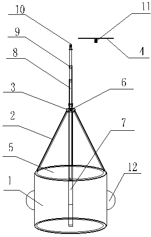
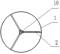
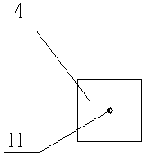
[0020] Such as figure 1 As shown in -3, the portable support device for static load test dial indicator of the present invention includes a base 1, 3 legs 2, a connecting device 3, a telescopic device and a support platform 4, and the bottoms of the 3 legs 2 are respectively welded to the base 1. At the trisection point of the edge, the telescopic device includes three telescopic rods 8 with different diameters connected sequentially from top to bottom. The bottom of the previous telescopic rod 8 is sleeved on the top of the next telescopic rod 8, and connected A locking device 9 is provided at the top, a threaded wire rod 10 is provided on the top of a telescopic rod 8 on the top, an opening 5 is provided on the upper end of the base 1, and the tops of the three legs 2 are connected and fixed by the connecting device 3, and the connection The center of the device 3 is provided with a central hole 6, the upper part of the connecting device 3 is connected with the telescopic ro...


PUM


Abstract

The invention discloses a portable supporting device for a static load test dial indicator, and the portable supporting device is characterized by comprising a base, a plurality of supporting legs, a connection device, a stretching device and a supporting platform, wherein the bottoms of the supporting legs are fixedly connected to the edge of the base, the tops of the supporting legs are fixed through the connection of the connection device, the center of the connection device is provided with a central hole, the upper part of the connection device is connected with the stretching device through the central hole, the lower part of the connection device is connected with a supporting tube, the bottom of the supporting tube is fixedly connected with the bottom of the base in a welding way, the stretching device comprises a plurality of stretching rods with identical diameter, the bottom of the previous stretching rod is sleeved on the top part of the next stretching rod, the junction of the two adjacent stretching rod is provided with a locking device, the top end of the uppermost stretching rod is provided with a metal lead screw with threads, the center on the bottom of the supporting platform is provided with a screw cap in a welding way, and the supporting platform is connected with the metal lead screw with the threads on the top end of the uppermost stretching rod through the screw cap. The portable supporting device has advantages of simpleness and safety in operation, high stability and convenience and accuracy in reading.

Description

technical field [0001] The invention relates to a portable supporting device for a static load test dial gauge. Background technique [0002] When doing the static load test of components such as floors and beams, it is necessary to closely contact the contacts of the dial indicator with the components, but the distance between the ground and the components is often more than three meters high, and only the original small bracket of the dial indicator is far away. It is far from enough. At present, inspection agencies spend a lot of manpower and material resources to build scaffolding or mobile scaffolding every time they do static load tests. Especially when making multiple floors, beams and other components, it not only consumes a lot of time, but also makes the working space narrow and inconvenient. Recording data, and even encountering scaffolding when reading data leads to experiment redoing, which is extremely inefficient. Therefore, a technical solution should be...

Claims


Application Information

Patent Timeline
Patent Type & Authority Applications(China)
IPC IPC(8): G01M13/00
Inventor 龚燕华梁晓晖崔建生李戬卢洋洋施洪亮杨陈玲
Owner NANTONG ACADEMY OF BUILDING RES
Features
  • R&D
  • Intellectual Property
  • Life Sciences
  • Materials
  • Tech Scout
  • Unparalleled Data Quality
  • Higher Quality Content
  • 60% Fewer Hallucinations
Learn More