Longitudinal magnetization moving coil device for plain shaft and crank shaft magnetic particle inspection

A technology of longitudinal magnetization and magnetic particle inspection, applied in the direction of material magnetic variables, etc., can solve the problems of easy damage, easy ignition, safety accidents and so on

Active Publication Date: 2012-10-03
YANCHENG ELECTRONICS EQUIP FACTORY
View PDF5 Cites 5 Cited by
  • Summary
  • Abstract
  • Description
  • Claims
  • Application Information

AI Technical Summary

Problems solved by technology

Due to the split-type opening and closing coil structure, when the opening and closing coil is closed and energized, it is easy to catch fire at the closed place, which often leads to fire and safety accidents
In addition, because the o

Method used


Image

  • Longitudinal magnetization moving coil device for plain shaft and crank shaft magnetic particle inspection
  • Longitudinal magnetization moving coil device for plain shaft and crank shaft magnetic particle inspection
  • Longitudinal magnetization moving coil device for plain shaft and crank shaft magnetic particle inspection

Examples


Embodiment Construction

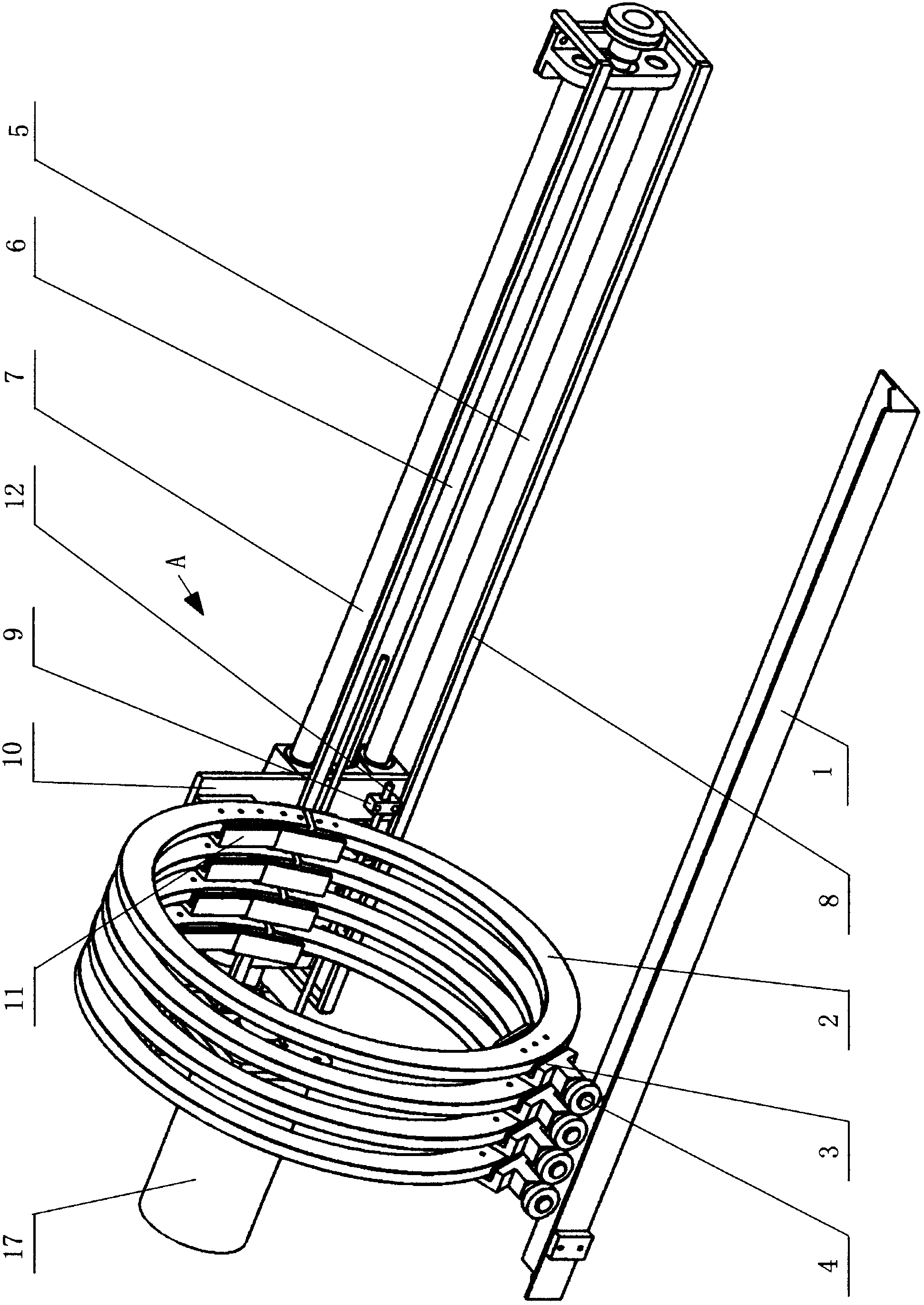
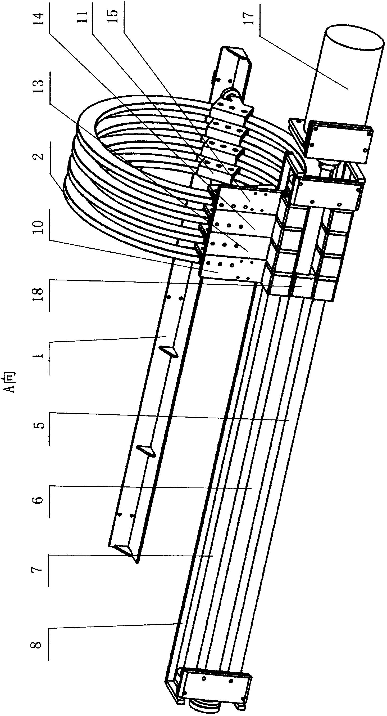
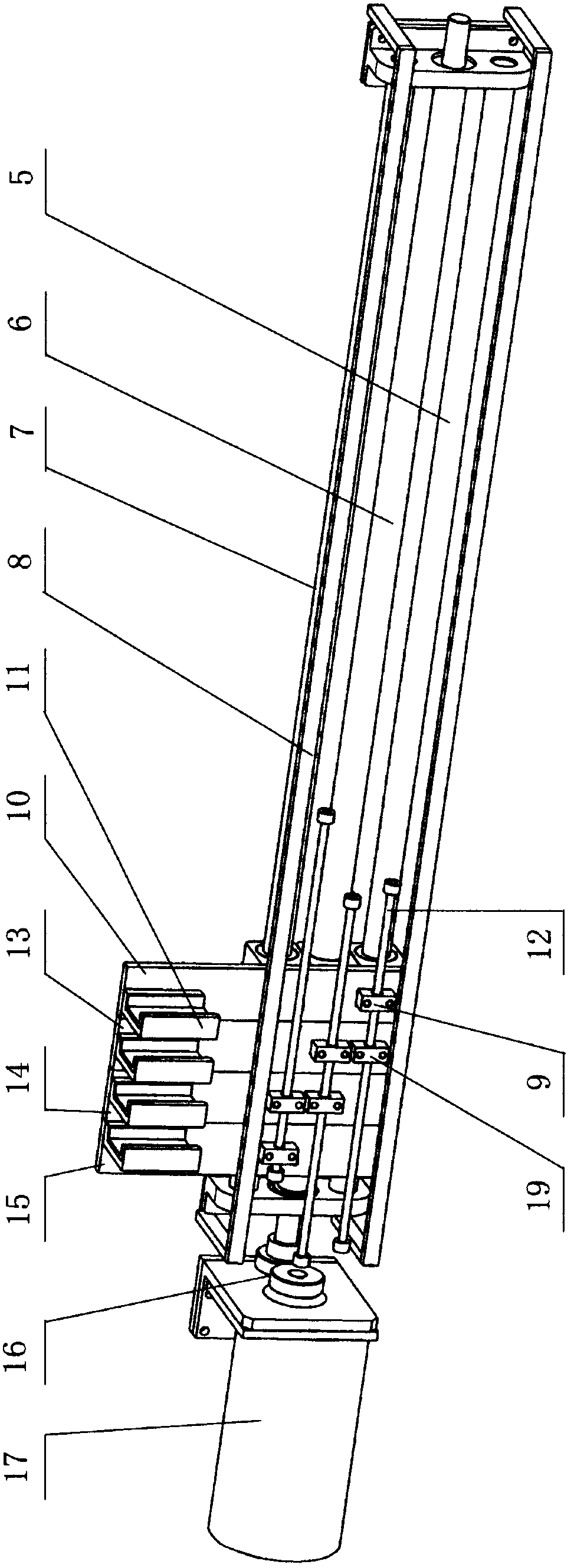
[0013] figure 1 , figure 2 and image 3 Among them, a longitudinal magnetization moving coil device for optical axis and crankshaft magnetic particle flaw detection, which includes several longitudinal magnetization coils 2, and also includes a moving mechanism and a guide rail 1. The longitudinal magnetization coil 2 is a circular overall structure. The guide rail 1 is located on the front side of the longitudinal magnetization coil 2 . The moving mechanism contains a motor 17, a support 8, two guide rods, a screw mandrel 6, a connecting rod 12, a coil connecting frame and a coil moving frame. The support 8 is positioned at the rear side of the longitudinal magnetization coil 2, and the two ends of the screw mandrel 6 are arranged on the left end and the right end of the support 8 respectively, and two guide rods, i.e., the upper guide rod 7 and the lower guide rod 5, are located at the ends of the screw rod 6 respectively. Above and below, the two ends of the upper guid...


PUM


Abstract

The invention discloses a longitudinal magnetization moving coil device for plain shaft and crank shaft magnetic particle inspection. The longitudinal magnetization moving coil device comprises a plurality of longitudinal magnetization coils, a moving mechanism and a guide rail, wherein each longitudinal magnetization coil has a round integral structure; the guide rail is positioned on the front side of the longitudinal magnetization coils; the moving mechanism comprises a motor, a support, two guide rods, a screw rod, a connecting rod, coil connecting frames and a coil moving frame; the support is positioned on the back side of the longitudinal magnetization coils; the motor is connected with the left end of the screw rod through a driving device; an upper shaft sleeve and a lower shaft sleeve are arranged on the coil connecting frames, and are respectively sleeved on the two guide rods which are positioned on the support; the quantity of the coil connecting frames is the same as that of the longitudinal magnetization coils; a coil trough is formed on each coil connecting frame; the back sides of the longitudinal magnetization coils are buckled in the troughs of the back sides; coil troughs and a guide wheel are arranged on the coil moving frame; the front sides of the longitudinal magnetization coils are buckled in the coil troughs; and the guide wheel of the coil moving frame is positioned on the guide rail.

Description

technical field [0001] The invention relates to a magnetic particle flaw detection machine, in particular to a longitudinal magnetization moving coil device for optical axis and crankshaft magnetic particle flaw detection in the magnetic particle flaw detection machine. Background technique [0002] An existing flaw detection machine that can be used for magnetic particle flaw detection of optical shafts and crankshafts contains several longitudinal magnetized coils, and the longitudinal magnetized coils are horizontally arranged in a row. The longitudinal magnetizing coil usually adopts the structure form of two semicircular split split coils. Due to the split-type opening and closing coil structure, when the opening and closing coil is closed and energized, it is easy to catch fire at the closed place, which often leads to fire and safety accidents. In addition, because the opening and closing coils are easy to catch fire at the closed position, the contact parts of the o...

Claims


Application Information

Patent Timeline
IPC IPC(8): G01N27/84
Inventor 程伟刘于海
Owner YANCHENG ELECTRONICS EQUIP FACTORY
Why Eureka
Try Eureka