Light emitting diode equipment

A technology of light-emitting diodes and substrates, which is applied in the direction of semiconductor devices, electrical components, circuits, etc., can solve the problem that the LED light emission angle cannot be significantly improved, and achieve the effects of improved reliability, high reliability, and increased light-emitting angle

Inactive Publication Date: 2012-10-03
GOERTEK INC
View PDF5 Cites 4 Cited by
  • Summary
  • Abstract
  • Description
  • Claims
  • Application Information

AI Technical Summary

Problems solved by technology

In addition to using metal (or electroplating gold, silver) for bracket 1, in consideration of high temperature resistance, easy molding and reflectivity of the product, white injection molding material (PPA or PA6T, PA9T, etc.) is generally used as the main material, but in this case, like figure 1 As shown, the light emitted by the LED can only be emitted through the continuous reflection in the opaque bowl, so a large amount of light will be absorbed inside the LED. At the same time, due to the influence of the depth of the bowl, the light angle of the LED cannot be significantly improved.

Method used


Image

  • Light emitting diode equipment
  • Light emitting diode equipment
  • Light emitting diode equipment

Examples


Embodiment Construction

[0014] The light emitting diode device of the present invention will be described in detail below with reference to the accompanying drawings.

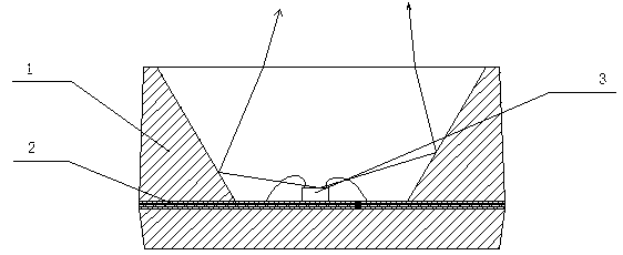
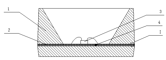
[0015] see figure 2 The light-emitting diode device of the present invention includes: a substrate 2, an insulating layer is arranged on the substrate 2, and a conductive layer is arranged on the insulating layer, the conductive layer includes a positive electrode conductive layer and a negative electrode conductive layer, and the positive and negative electrode conductive layers pass through the insulating partition 4 Insulated and separated; the bracket 1, the bracket 1 forms a concave opening, and the bracket 1 and the substrate 2 together form a bowl structure of the light-emitting diode device; the light-emitting diode chip 3, the light-emitting diode chip 3 is arranged on the substrate 2, and the light-emitting diode chip 3 is positive The negative electrode is electrically connected to the positive and negative conductive laye...


PUM


Abstract

The invention discloses light emitting diode equipment, which comprises a substrate, a bracket and a light emitting diode chip, wherein an insulation layer and a conductive layer arranged thereon are both arranged on the substrate; the bracket forms a concave opening and a light projecting hole of the bowl structure of the light emitting diode together with the substrate; the light emitting diode is arranged on the substrate and electrically connected with the conductive layer; the bracket adopts a transparent material; the bowl structure of the light emitting diode is transparent; and a light emitting from the light emitting diode can emit out of the bowl structure. The light emitting diode has the advantages of large light quantity and emitting angle.

Description

technical field [0001] The invention relates to a light emitting diode device, in particular to a light emitting diode device with large luminous flux and large light emitting angle. Background technique [0002] With the development and maturity of light emitting diode (Light Emitting Diode, LED) technology, the application fields of LED devices are becoming more and more extensive, and people's requirements for LEDs are also getting higher and higher. [0003] Traditionally designed LEDs such as figure 1 As mentioned above, it generally includes a bracket 1, a substrate 2, an LED chip 3 and encapsulation glue (not shown in the figure); the bracket 1 and the substrate 2 are combined to form a bowl and cup structure. In addition to using metal (or electroplating gold, silver) for bracket 1, in consideration of high temperature resistance, easy molding and reflectivity of the product, white injection molding material (PPA or PA6T, PA9T, etc.) is generally used as the main ma...

Claims


Application Information

Patent Timeline
Patent Type & Authority Applications(China)
IPC IPC(8): H01L33/48H01L33/56
Inventor 安国顺张道峰
Owner GOERTEK INC
Why Eureka
Try Eureka