Pile-driving method and vibration control method

A control method and pile head technology, which can be applied in the direction of sheet pile wall, building, foundation structure engineering, etc., can solve the problems that the pile head wave node method is difficult to be practical, and achieve easy practical application, reduce the possibility of failure, and easy construction Effect

Active Publication Date: 2014-06-18
NIPPON STEEL CORP
View PDF12 Cites 0 Cited by
  • Summary
  • Abstract
  • Description
  • Claims
  • Application Information

AI Technical Summary

Problems solved by technology

Therefore, there is a problem that the pile head wave node method is difficult to be practical

Method used


Image

  • Pile-driving method and vibration control method
  • Pile-driving method and vibration control method
  • Pile-driving method and vibration control method

Examples


Embodiment

[0064] Next, examples of the present invention will be described.

[0065] In this example, the effect obtained by applying a load to the pile head Ph was confirmed.

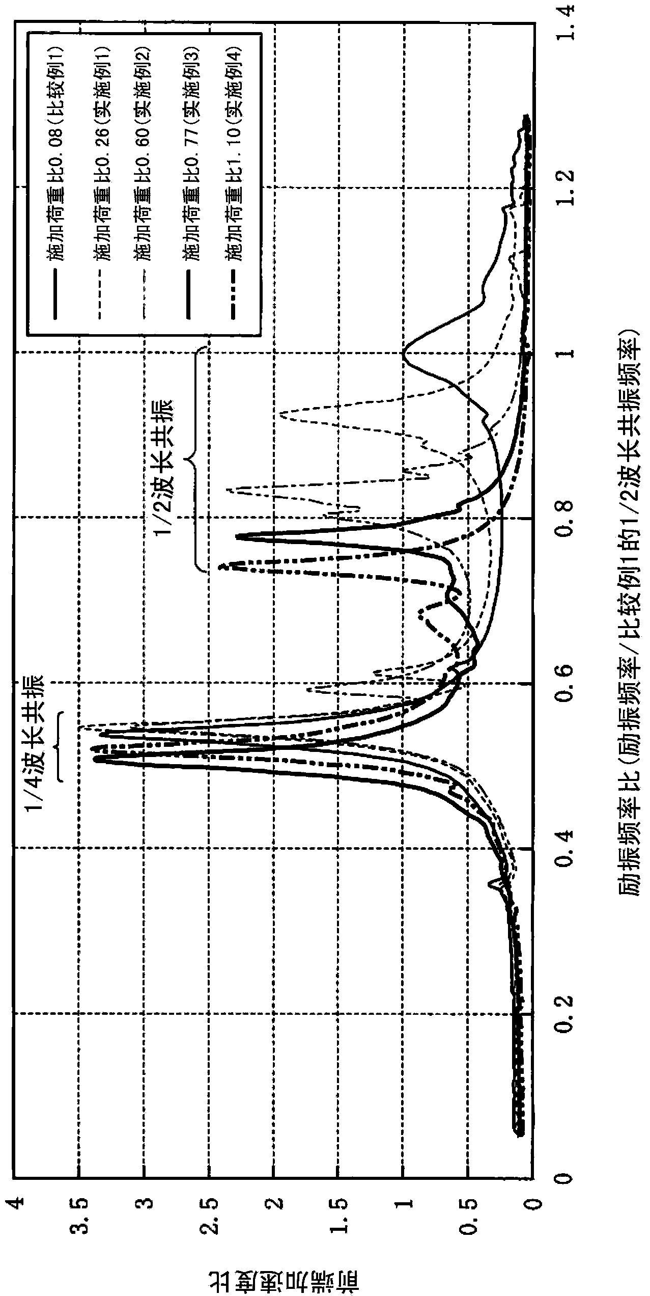
[0066] First, the relationship between the load applied to the pile P, the resonance frequency of the pile P, and the acceleration of the pile tip Pf during excitation (hereinafter simply referred to as tip acceleration) is confirmed.

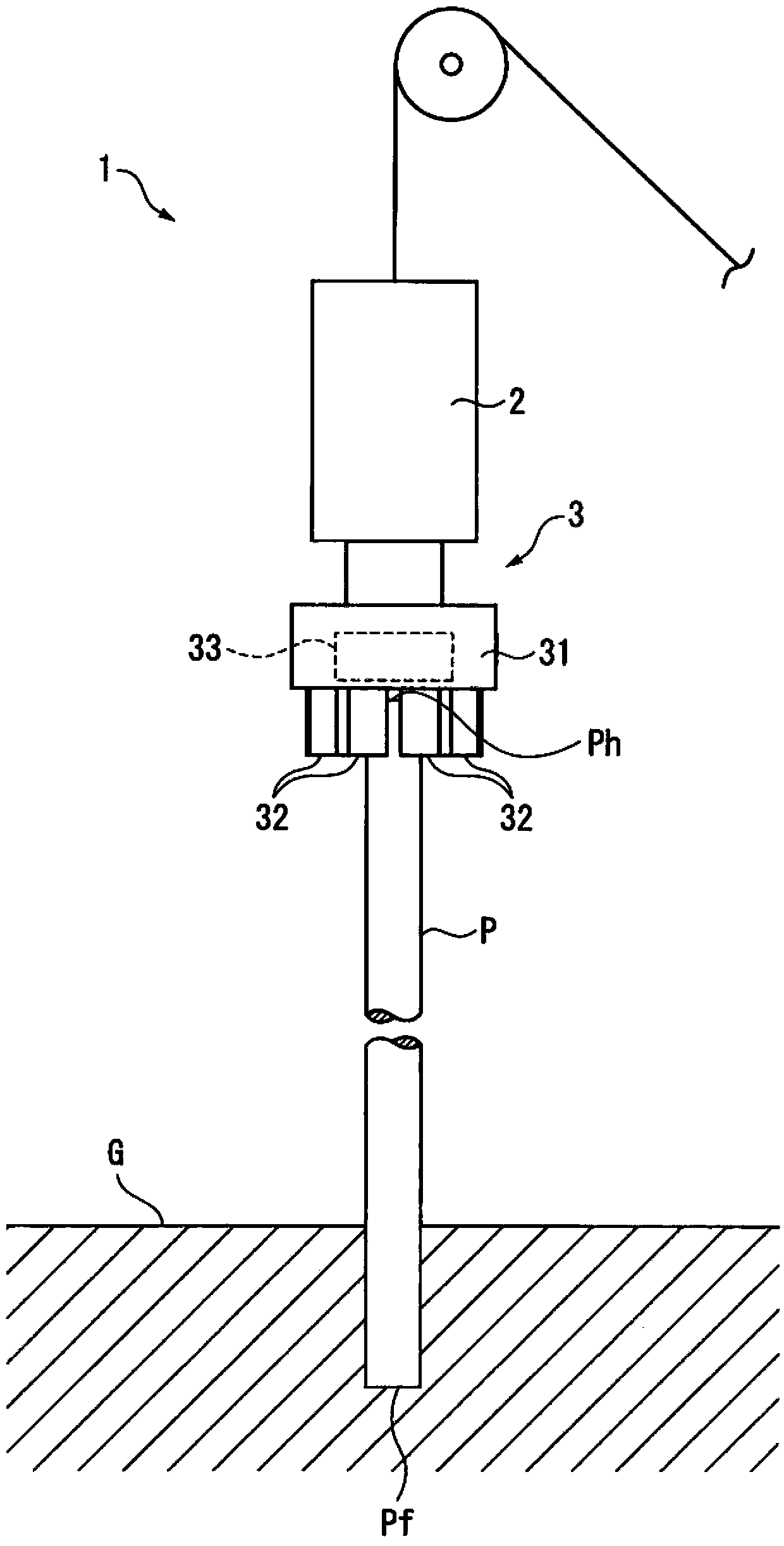
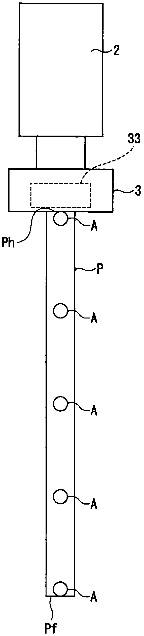
[0067] Such as figure 2 As shown, the accelerometers A are installed at five locations along the length direction of the pile P at equal intervals from each other. Moreover, this pile P is gripped by the pile gripping apparatus 3 attached to the front-end|tip of the vibrator 2. As shown in FIG. In addition, the values ​​obtained by dividing the sum of the mass of the pile grasping device 3 and the weight 33 by the mass of the pile P (hereinafter simply referred to as the applied load ratio) are installed on the pile grasping device 3. . And, make the power of the exciter 2 c...


PUM


Abstract

Provided is a pile-driving method that makes use of sympathetic vibrations along the length of a pile to drive the pile into the ground. A load is applied to the head of a pile, said load being equivalent to between 0.26 and 3 times the mass of the pile, and the pile is vibrated by means of sympathetic vibrations corresponding to a resonance mode in which the top of the pile is an antinode.

Description

technical field [0001] The invention relates to a pile driving method for driving piles into the ground by using resonance vibration, and an excitation control method for controlling the vibration of piles when driving piles into the ground. [0002] This application is based on Japanese Patent Application No. 2010-007054 for which it applied in Japan on January 15, 2010, and the priority is claimed, The content is used in this specification. Background technique [0003] Conventionally, there is known a resonance vibration pile driving method in which a pile is driven into the ground by vibrating the pile with a pile driver. In this resonance vibration pile driving method, first, the excitation frequency applied to the pile is made to coincide with the natural frequency in the longitudinal direction of the pile. Next, piles are driven into the ground using resonant vibrations generated by matching the excitation frequency with the natural frequency. This resonance piling ...

Claims


Application Information

Patent Timeline
Patent Type & Authority Patents(China)
IPC IPC(8): E02D7/18
CPCE02D7/18
Inventor 森安俊介妙中真治辻井正人
Owner NIPPON STEEL CORP
Why Eureka
Try Eureka