Device for generating electric energy from a heat-conducting material

A technology of electric energy and thermoelectric elements, which is applied in the field of devices that generate electric energy from thermal energy, and can solve problems such as insufficient electric energy efficiency

Active Publication Date: 2012-10-03
EMITEC GESELLSCHAFT FUR EMISSIONSTECHNOLOGIE MBH
View PDF3 Cites 2 Cited by
  • Summary
  • Abstract
  • Description
  • Claims
  • Application Information

AI Technical Summary

Problems solved by technology

But so far, electricity generation from this heat source has not been efficient enough

Method used


Image

  • Device for generating electric energy from a heat-conducting material
  • Device for generating electric energy from a heat-conducting material
  • Device for generating electric energy from a heat-conducting material

Examples


Embodiment Construction

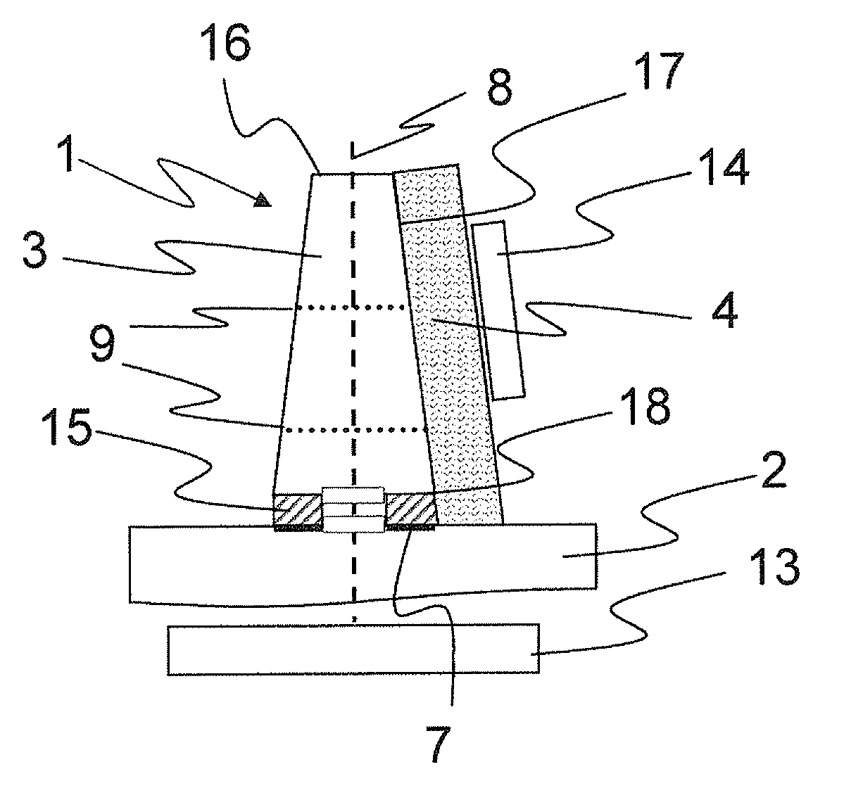
[0055] figure 1 A first variant of the embodiment of the device 1 is shown with a body 2 heated by a heating device 13 , for example a burner, and a projection laterally connected with a thermoelectric element 4 cooled by a cooling device 14 3. The elevation 3 is separated from the heated body 2 in a local point 7 by a second thermal insulation 15 , whereby temperature peaks at the base 18 of the elevation 3 can be avoided. Furthermore, the protrusions 3 have different cross sections 9 along their axial direction 8 , whereby the heat output delivered by the protrusions 3 is adapted to the efficiency of the thermoelectric element 4 . For the variant shown here, the thermoelectric element 4 extends from the bottom 18 along the circumferential surface 17 to the front 16 of the protrusion 3 . In principle, however, the number and orientation or position of the thermoelectric elements 4 may vary for adaptation purposes.

[0056] The figures referred to below show to a certain ex...


PUM


Abstract

The invention relates to a device (1) for generating electric energy, comprising at least one heated heat-conducting base (2) having at least one projection (3) and thermoelectric elements (4) which are laterally attached to the at least one projection (3), a thermoelectric efficiency of every thermoelectric element (4) and a thermal capacity of the at least one projection (3) being matched to each other.

Description

technical field [0001] The invention relates to a device for generating electrical energy from thermal energy, which has a thermally conductive material. Such devices are, for example, thermoelectric generators which can be used in the exhaust system of an internal combustion engine of a motor vehicle. Background technique [0002] In the exhaust gas treatment of mobile internal combustion engines, such as gasoline or diesel engines, attempts are currently being made to treat the exhaust gas in such a way that it is already almost completely purified when it is discharged into the environment. Attempts are also made to convert any form of unused emitted energy into a usable form of energy. [0003] Exhaust gases from motor vehicle engines have thermal energy which can be transferred by thermal contact to heat-conducting materials and converted into electrical energy by thermoelectric generators, for example to charge batteries or other electrical energy storage devices and / ...

Claims


Application Information

Patent Timeline
Patent Type & Authority Applications(China)
IPC IPC(8): H01L35/30
CPCH01L35/30H10N10/13
Inventor 罗尔夫·布吕克西格丽德·利姆贝克
Owner EMITEC GESELLSCHAFT FUR EMISSIONSTECHNOLOGIE MBH
Why Eureka
Try Eureka