

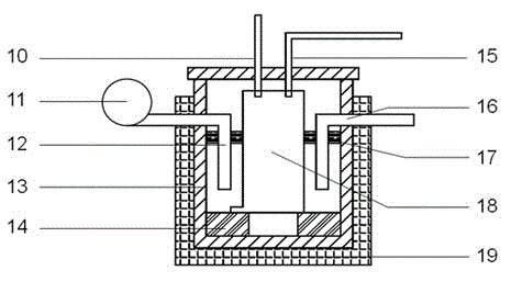
Direct carbon fuel cell device with liquid metal tin serving as anode
A liquid metal and fuel cell technology, applied in solid electrolyte fuel cells, battery electrodes, circuits, etc., can solve the problems of limiting anode mass transfer efficiency and limited contact area, and achieve the effect of improving anode mass transfer performance
- Summary
- Abstract
- Description
- Claims
- Application Information
AI Technical Summary
Problems solved by technology
Method used
Image

Examples
Embodiment 1
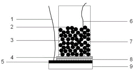
[0029] Example 1: Using carbon black as carbon fuel, mix it with tin powder at a mass ratio of 20:3 and add it into the fuel chamber of a straight carbon fuel cell with liquid metal tin as the anode, and seal the battery device. At normal temperature, nitrogen gas is passed into the anode to remove the air in the anode cavity. Turn on the heater, and when the temperature rises to 500°C, air is introduced into the cathode cavity with an air pressure of 0.5Mpa, and the working conditions of the battery are recorded. The discharge performance of the battery at 750°C is listed here, see attached table 1.
Embodiment 2
[0030] Example 2: Using carbon black as carbon fuel, mix it with tin powder at a mass ratio of 6:1 and add it into the fuel chamber of a direct carbon fuel cell with liquid metal tin as the anode, and seal the battery device. At normal temperature, nitrogen gas is passed into the anode to remove the air in the anode cavity. Turn on the heater, and when the temperature rises to 500°C, air is introduced into the cathode cavity with an air pressure of 0.5Mpa, and the working conditions of the battery are recorded. The discharge performance of the battery at 750°C is listed here, see attached table 1.
Embodiment 3
[0031] Example 3: Using carbon black as carbon fuel, mix it with tin powder at a mass ratio of 11:1 and add it into the fuel chamber of a straight carbon fuel cell with liquid metal tin as the anode, and seal the battery device. At normal temperature, nitrogen gas is passed into the anode to remove the air in the anode cavity. Turn on the heater, and when the temperature rises to 500°C, air is introduced into the cathode cavity with an air pressure of 0.5Mpa, and the working conditions of the battery are recorded. Now list the discharge performance of the battery at 800°C, see attached table 1.
[0032]
[0033] Table 1 is as follows:
[0034] Example Tin: carbon (mass ratio) temperature Maximum current density Maximum Power Density average power density 1 20:3 750 5.37mA / cm 2 4.75mW / cm 2 4.53mW / cm 2 2 6:1 750 9.61mA / cm 2 9.11mW / cm 2 8.64mW / cm 2 3 11:1 800 10.02mA / cm 2 9.90mW / cm 2 8.45mW / cm 2
PUM
| Property | Measurement | Unit |
|---|---|---|
| particle diameter | aaaaa | aaaaa |
| particle diameter | aaaaa | aaaaa |
Abstract
Description
Claims
Application Information