
Fixture on lockset perforating machine

A punching machine and fixture technology, applied in the direction of clamping, manufacturing tools, metal processing machinery parts, etc., can solve the problems of low processing efficiency and processing accuracy, affecting the accuracy of punching, affecting the qualification rate of locks, etc., to improve the processing efficiency. Efficiency and machining accuracy, novel structure, and the effect of improving accuracy

Active Publication Date: 2012-10-17
安徽格太信控科技有限公司
View PDF6 Cites 4 Cited by
  • Summary
  • Abstract
  • Description
  • Claims
  • Application Information

AI Technical Summary

Problems solved by technology

During processing, the lock is fixed on the fixture, and the drill bit on the punching machine punches the lock body, and the drill bit has to be picked up once each hole is drilled. At this time, the fixture needs to be loosened to move the lock body position, and the processing efficiency and precision are low.
Due to the error in the length of the lock shell and the depth of the lock cylinder hole on the lock, errors often occur when the lock is fixed on the fixture or moved, which affects the accuracy of drilling, and then affects the qualified rate of lock processing.

Method used


Image

  • Fixture on lockset perforating machine

Examples


Embodiment Construction

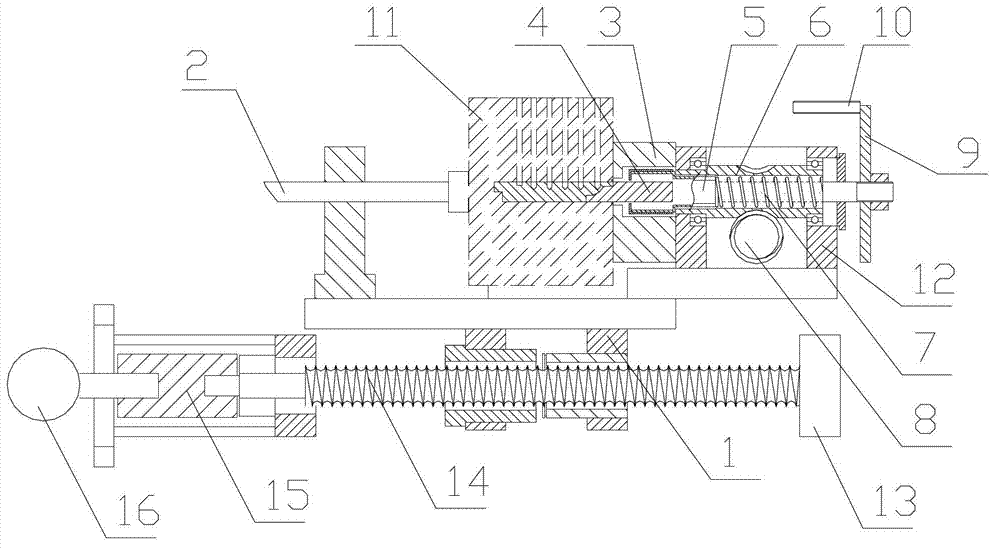
[0009] Attached below figure 1 The present invention is further described.

[0010] like figure 1 The clamp on the lock drilling machine shown is composed of a clamp moving device and a position adjusting device, and the position adjusting device is installed on the clamp moving device.

[0011] Fixture moving device comprises motor 16, coupling 15, screw mandrel 14, mounting frame 13, slide block 1, movable clamping block 2 and fixed clamping block 3, and screw mandrel 14 is contained on the mounting frame 13, and motor 16 passes through joint. The shaft device 15 is connected with the screw mandrel 13, the slide block 1 is installed on the screw mandrel 13, the motor 16 drives the slide block 1 to move through the screw mandrel 14, the movable clamping block 2 and the fixed clamping block 3 are assembled on the slide block 1, to be The processed lockset 11 is between the movable clamping block 2 and the fixed clamping block 3 .

[0012] The position adjustment device incl...


PUM


Abstract

The invention relates to a lockset perforating machine. The fixture on lockset perforating machine comprises a fixture moving device and a position adjusting device, wherein the position adjusting device is installed on the fixture moving device; the fixture moving device comprises a motor, a lead screw, a mounting frame, a slide block, a movable clamping block and a fixed clamping block; and the position adjusting device comprises an enclosure, a worm, a worm wheel, a rotating shaft, a rotating core, a drive motor, a locating plate, a pressure spring and an adjusting bolt. The fixture on lockset perforating machine has the advantages that structure is novel and the lockset perforating precision is improved.

Description

technical field [0001] The invention relates to, in particular, a lock punching machine. Background technique [0002] When the lock is produced, a row of pinholes needs to be punched on the lock body, and the lock cylinder on the lock body is connected with the pinholes. During processing, the lockset is fixed on the fixture, and the drill bit on the drilling machine punches the lock body, and the drill bit will be picked up once every time a hole is punched. At this time, the fixture needs to be loosened to move the lock body position, and the processing efficiency and precision are low. Due to the error in the length of the lock shell and the depth of the lock cylinder hole on the lock, errors often occur when the lock is fixed on the fixture or moved, which affects the accuracy of drilling, and then affects the qualified rate of lock processing. Contents of the invention [0003] The object of the present invention is to solve the above-mentioned deficiencies in the e...

Claims


Application Information

Patent Timeline
IPC IPC(8): B23Q3/00B23Q5/40
Inventor 张必葵
Owner 安徽格太信控科技有限公司
Learn More