
Elevator equipment

An equipment and elevator technology, which is applied to elevators, transportation and packaging in buildings, etc., can solve the problems of unstable transmission, danger, sudden movement and sudden stop, etc., to avoid mutual influence, improve safety, and facilitate operation. Effect

Inactive Publication Date: 2015-06-03
佛山市欧贝斯无障碍科技有限公司
View PDF10 Cites 0 Cited by
  • Summary
  • Abstract
  • Description
  • Claims
  • Application Information

AI Technical Summary

Problems solved by technology

The cable transmission is difficult to install, complicated to control, and requires a large investment. It is suitable for public environments with a large number of people; the transmission mode of the hydraulic cylinder is a single-point support and single-side transmission mode, and the transmission is not stable enough, and there are sudden movements and sudden stops.
[0003] For this reason, I have applied for a patent about a home elevator driven by rack and pinion, but there are still deficiencies in this scheme, such as: 1. The motor is connected with two gears through a reduction box, and the two gears are respectively parallel to the two gears in the elevator shaft. And the vertically arranged racks mesh, which leads to the lack of high processing precision requirements for racks and racks, and high installation requirements for racks. Once the above two conditions are not met, the elevator will not run smoothly; 2. In the plan, it is only roughly introduced that it can A hand crank is installed at the end of the motor. However, since the motor is located on the upper part of the car, even if the hand crank is installed, the user cannot operate it when the power is off. Moreover, when the motor rotates, the hand crank will rotate at a high speed, which will 3. Since the motor is a brake motor, it will lock itself when the power is off, so the hand crank cannot drive the motor to rotate

Method used


Image

  • Elevator equipment
  • Elevator equipment
  • Elevator equipment

Examples


Embodiment Construction

[0026] The present invention will be further described below in conjunction with the accompanying drawings and embodiments.

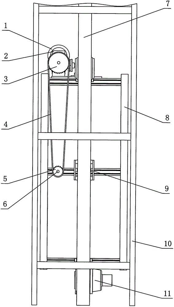
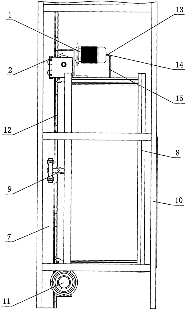
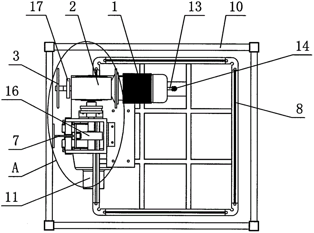
[0027] see Figure 1-6 , the elevator equipment includes a car 8, the car is provided with a motor 1, the motor is connected to the drive gear 16 through a transmission mechanism, and the drive gear is engaged with the rack 12 vertically arranged in the hoistway frame 10; Also be provided with and be used for controlling the manual rotating shaft 6 of car lifting motion, manual rotating shaft is connected with driving gear through clutch 17 and described transmission mechanism.

[0028] Described manual rotating shaft 6 is positioned at the middle position of car 8, and its one end stretches into the car, and the other end is connected with clutch 17 by speed reduction mechanism. Described deceleration mechanism comprises large sprocket 3, small sprocket 5 and chain 4, and large sprocket is connected with clutch 17, and small sprocket is connected with...


PUM


Abstract

The invention discloses elevator equipment. The elevator equipment comprises a cage which is provided with a motor; the motor is connected with a drive gear through a transmission mechanism; the drive gear is meshed with a rack arranged in a well frame in a longitudinal direction; and a manual rotation shaft which is used for controlling the cage to lift is arranged on the cage and is connected with the drive gear through a clutch and the transmission mechanism. The elevator equipment has the advantages that 1) the elevator equipment is provided with the manual rotation shaft, so that during power failure of an elevator, the elevator is driven by rotating the manual rotation shaft to lift so as to achieve the leveling effect; the clutch is arranged between the manual rotation shaft and the drive gear, so that two mechanisms are driven in an electronic control or manual operation way to be separated to work, and the mutual influence is avoided; and 2) the manual rotation shat extends to the middle position of the cage through a reducing mechanism, so that a user can operate the elevator equipment conveniently, and labor is saved during operation.

Description

technical field [0001] The present invention relates to an elevator installation, mainly a domestic elevator installation. Background technique [0002] Elevator equipment currently on the market has cable transmission, hydraulic cylinder transmission, etc., and there is no manual lifting elevator equipment in the form of single rack and pinion transmission. The cable transmission is difficult to install, complicated to control, and requires a large investment. It is suitable for public environments with a large number of people; the transmission mode of the hydraulic cylinder is a single-point support and unilateral transmission mode, and the transmission is not stable enough, and there are sudden movements and sudden stops. [0003] For this reason, I have applied for a patent about a home elevator driven by rack and pinion, but there are still deficiencies in this scheme, such as: 1. The motor is connected with two gears through a reduction box, and the two gears are resp...

Claims


Application Information

Patent Timeline
Patent Type & Authority Patents(China)
IPC IPC(8): B66B11/04
Inventor 林澄海
Owner 佛山市欧贝斯无障碍科技有限公司
Learn More