Vibration and pressure well drilling tool

A technology for drilling tools and driving rods, applied in vibration drilling, etc., can solve the problems of increased drilling tool structure complexity, increased drilling fluid damping and top torque negative feedback, accelerated PDC bit damage and failure, etc.

Active Publication Date: 2012-10-17
CHINA UNIV OF PETROLEUM (EAST CHINA)
View PDF9 Cites 16 Cited by
  • Summary
  • Abstract
  • Description
  • Claims
  • Application Information

AI Technical Summary

Problems solved by technology

[0002] PDC drill bit (English abbreviation for Polycrystalline Diamond Compact, polycrystalline diamond compact drill bit) is an efficient rock-breaking tool with fast drilling speed, long service life and good working stability. However, with the advancement of oil exploration and development to deep formations , the increase in hard formations, complex formations, and the complexity of drill tool structures has accelerated the damage and failure of the PDC bit, and the "stick-slip" vibration of the drill string (that is, the continuous accumulation and instantaneous release of the drill string torque) is the cause of the PDC The main cause of drill bit failure; conventional measures to eliminate the "stick-slip" vibration of PDC drill bits mainly include: increasing the drill string speed, optimizing the drill tool structure, increasing drilling fluid damping and top torque negative feedback, etc., but the above technical measures all exist Certain limitations, it is difficult to fundamentally solve the problem

Method used


Image

  • Vibration and pressure well drilling tool

Examples


Embodiment Construction

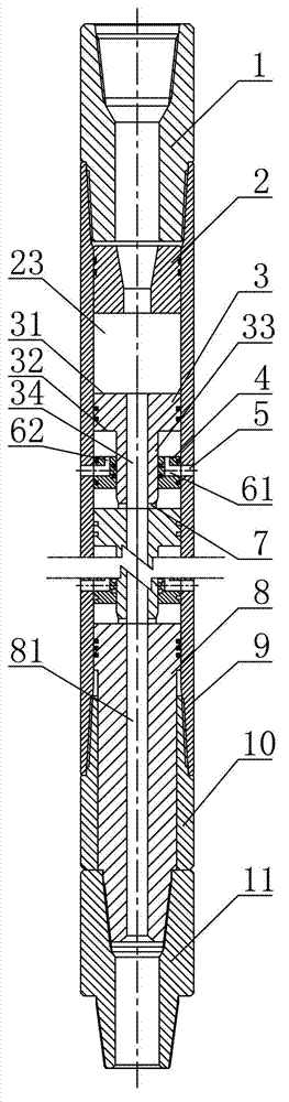
[0013] The following is a specific embodiment of a vibratory pressurized drilling tool of the present invention, which is used to explain but not limit the present invention; the place where the drilling fluid enters is defined as "upper" and the place where the drilling fluid exits is "down".

[0014] As shown in the accompanying drawings, a vibratory pressurized drilling tool includes a sleeve 9, an upper joint 1 is installed on the upper end of the sleeve 9, and a nozzle 2 is installed at the lower end of the upper joint 1 inside the sleeve 9, and the nozzle 2 has a hollow The nozzle channel, wherein the inlet of the nozzle channel is larger than its outlet, is divided into an upper conical section and a lower cylindrical end; the lower end of the sleeve 9 is threaded with a driving nipple 10, the sleeve 9 and the driving nipple 10 A driving rod 8 is slidably installed, and the polygonal outline fits between the driving rod 8 and the inner wall of the driving nipple 10, whic...


PUM


Abstract

The invention discloses a vibration and pressure well drilling tool. An upper connector and a nozzle are arranged at the upper end of a sleeve; a driving rod is arranged at the lower end of the sleeve in a sliding manner; the lower end of the driving rod is fixedly connected with a lower connector; a plurality of stages of piston separation ring structures are arranged between the nozzle and the driving rod in the sleeve; each stage of piston separation ring structure comprises a piston approximately in a T-shaped structure, and a separation ring fixedly arranged in the sleeve and sleeved at a guide rod part of each piston; piston pressure transmitting holes communicated with a piston runner are arranged at the lower ends of the guide rod parts of the pistons; radial separation ring holes and axial separation ring holes are arranged in the separation rings; and sleeve flow guide holes are arranged in the sleeve, corresponding to the radial separation ring holes. According to the invention, shock vibration is innovatively introduced for ''stick-slip'' vibration of a drill bit, so that the stick-slip in the drilling process of the PDC (polycrystalline diamond compact) drill bit is eliminated, the PDC drill bit exerts a high-frequency and low-amplitude shock effect on the rock below, the stress status of the rock is improved, and the rock breaking efficiency is increased.

Description

technical field [0001] The invention relates to the technical field of supporting devices for oil and natural gas drilling, in particular to a vibration pressurized drilling tool. Background technique [0002] PDC drill bit (English abbreviation for Polycrystalline Diamond Compact, polycrystalline diamond compact drill bit) is an efficient rock-breaking tool with fast drilling speed, long service life and good working stability. However, with the advancement of oil exploration and development to deep formations , the increase in hard formations, complex formations, and the complexity of drill tool structures has accelerated the damage and failure of the PDC bit, and the "stick-slip" vibration of the drill string (that is, the continuous accumulation and instantaneous release of the drill string torque) is the cause of the PDC The main cause of drill bit failure; conventional measures to eliminate the "stick-slip" vibration of PDC drill bits mainly include: increasing the dri...

Claims


Application Information

Patent Timeline
Patent Type & Authority Applications(China)
IPC IPC(8): E21B7/24
Inventor 倪红坚王瑞和王鹏
Owner CHINA UNIV OF PETROLEUM (EAST CHINA)
Why Eureka
Try Eureka