
Wind power generation and wind power air compression dual-purpose machine with automatic speed regulation function

A technology of automatic speed regulation and air compression, which is applied to wind turbine components, wind turbines, wind turbines that are consistent with the wind direction, etc.

Inactive Publication Date: 2012-10-17
WEIHAI WEIYING PLASTIC
View PDF0 Cites 7 Cited by
  • Summary
  • Abstract
  • Description
  • Claims
  • Application Information

AI Technical Summary

Problems solved by technology

[0002] At present, most of the wind turbines produced and installed are above 20KW, and the speed regulation and wind direction adjustment are completed by complex intelligence, which has high investment costs. However, complex intelligence is rarely used to adjust the wind direction and wind direction for the units below 10KW. In this way, a simple method is adopted, and the tail rudder is installed to complete the wind turbine blades facing the wind direction. When encountering destructive wind speed, the tail rudder has to be manually pulled to change the wind turbine wind surface. The angle of the wind direction; moreover, the current production and installation of wind power generation and wind pumping, single-use is more common, can not achieve a multi-purpose machine

Method used


Image

  • Wind power generation and wind power air compression dual-purpose machine with automatic speed regulation function

Examples


Embodiment Construction

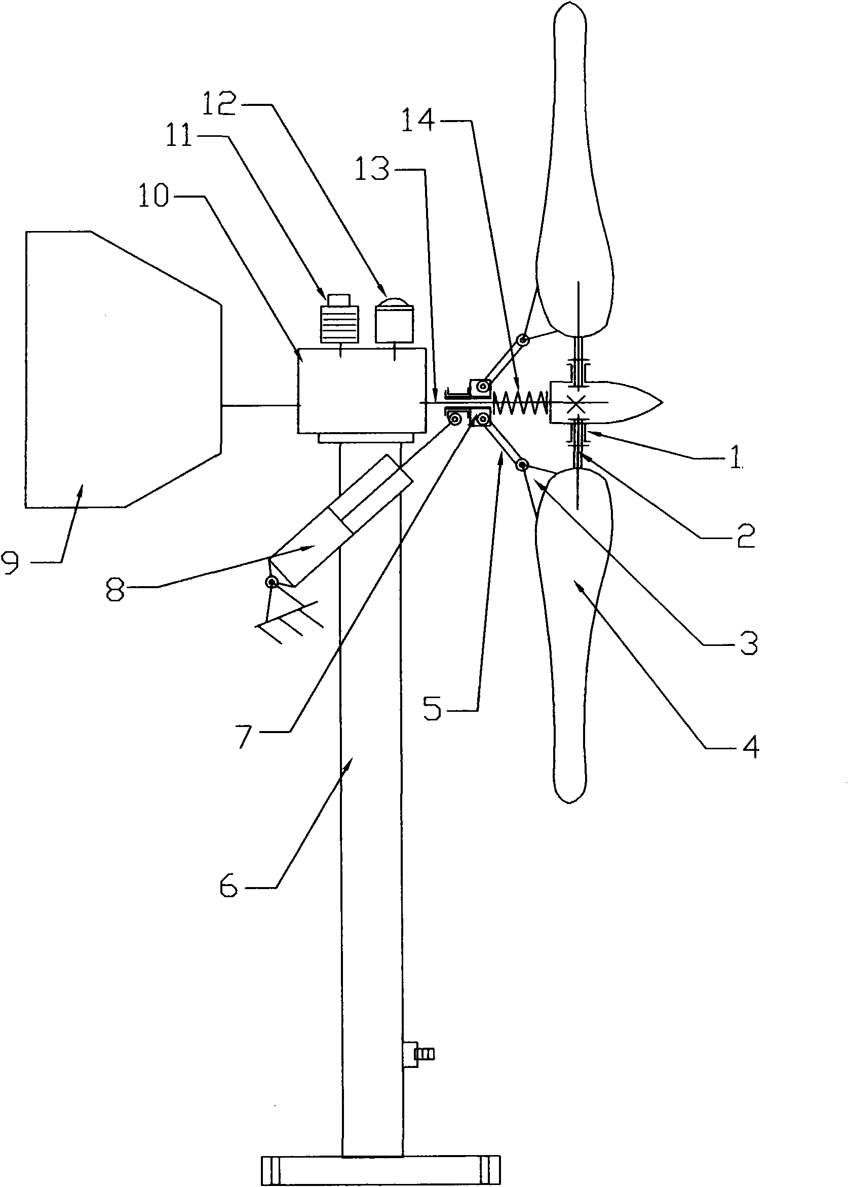
[0009] figure 1 As shown, the components for wind power generation are composed of fan blade 4, fan blade shaft 2, fan blade flange 1, adjustment arm 3, and power shaft 13; fan blade shaft 2 is connected to fan blade flange 1 through a radial bearing, and fan blade 4 can be wound When the shaft rotates, the power shaft 13 is equipped with an axially slidable blade angle adjustment sleeve 7, and the push rod of the cylinder 8 installed on the frame is connected with the adjustment sleeve 7, and the connecting rod 5 is used between the adjustment sleeve 7 and the adjustment arm 3. connection, the power shaft 13 is equipped with a preload spring 14, and the preload spring 14 is installed between the adjustment sleeve 7 and the fan blade flange 1. Under normal conditions, the adjustment sleeve 7 is pushed by the preload spring 14, and the fan blade is pulled by the connecting rod 5 Adjust the arm 3 so that the wind-receiving surface of the fan blade 4 and the wind direction have a...


PUM


Abstract

The invention belongs to the field of wind power energy and discloses a wind power generation and wind power air compression dual-purpose machine with an automatic speed regulation function. A power generating component consists of a fan blade (4), a rotating shaft (2), a flange (1), an adjusting arm (3) and a power shaft (13). The dual-purpose machine is characterized in that the rotating shaft (2) is connected with the flange (1) through a radial bearing, so that the fan blade (4) can rotate around the rotating shaft; an axial sliding adjusting sleeve (7) is arranged on the power shaft (13); a push rod of an air cylinder (8) is connected with the adjusting sleeve (7); a connecting rod (5) is connected with the adjusting sleeve (7) and the adjusting arm (3); a pre-pressing spring (14) is arranged between the adjusting sleeve (7) and the flange (1); the adjusting sleeve (7) is pushed by the pre-pressing spring (14) in a normal state; the connecting rod (5) pulls the adjusting arm (3), so that the fan blade (4) generates an angle at a rated rotating speed; when wind speed exceeds the rated rotating speed, the air pressure inside an upright rod (6) is increased, so that the air cylinder (8) works to overcome the resistance of the pre-pressing spring (14) so as to push the adjusting sleeve (7) to move forwards, the fan blade (4) is pushed to rotate around the rotating shaft (2), a windward angle of the fan blade (4) is reduced, and an effect of regulating the speed is achieved; and moreover, the upright rod (6) serves as an upright rod and a gearbox (10) which is arranged at the upper end of an air reservoir, and the power shaft (13) is connected into the gearbox (10) for increasing the speed, so that a generator (12) and an air compressor (11) are driven to work simultaneously.

Description

technical field [0001] The invention belongs to the field of wind power energy, specifically transforms wind energy into mechanical energy to do work, and invents a dual-purpose machine for wind power generation and wind air compression with automatic speed regulation. Background technique [0002] At present, most of the wind turbines produced and installed are above 20KW, and the speed regulation and wind direction adjustment are completed by complex intelligence, which has high investment costs. However, complex intelligence is rarely used to adjust the wind direction and wind direction for the units below 10KW. In this way, a simple method is adopted, and the tail rudder is installed to complete the wind turbine blades facing the wind direction. When encountering destructive wind speed, the tail rudder has to be manually pulled to change the wind turbine wind surface. The angle of the wind direction; and the wind power generation and wind pumping that are currently produ...

Claims


Application Information

Patent Timeline
Patent Type & Authority Applications(China)
IPC IPC(8): F03D1/02F03D7/04F03D11/04F03D9/00F03D9/25F03D9/28F03D15/00
CPCY02E10/723Y02E10/725Y02E10/728Y02E10/72
Inventor 黄道兴
Owner WEIHAI WEIYING PLASTIC
Learn More