Method for measuring signal phase difference

A signal phase and difference measurement technology, applied in the measurement device, measuring electrical variables, phase angle between voltage and current, etc., can solve problems such as poor applicability and high signal-to-noise ratio, and achieve high accuracy and fast calculation speed. Effect

Inactive Publication Date: 2012-10-17
INST OF SEMICONDUCTORS - CHINESE ACAD OF SCI
View PDF4 Cites 9 Cited by
  • Summary
  • Abstract
  • Description
  • Claims
  • Application Information

AI Technical Summary

Problems solved by technology

[0008] In summary, the applicant found that the prior art signal phase difference measurement method has the following defects: all require the measurement sample to have a high signal-to-noise ratio, and the applicability is poor

Method used


Image

  • Method for measuring signal phase difference
  • Method for measuring signal phase difference
  • Method for measuring signal phase difference

Examples


Embodiment Construction

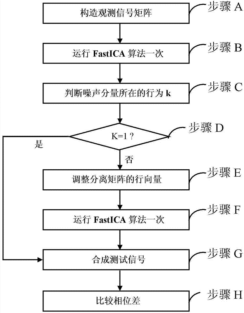
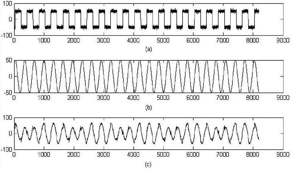
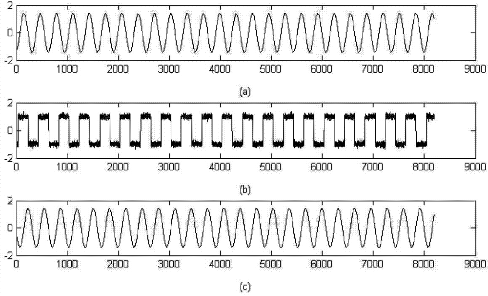
[0022] In order to make the objectives, technical solutions, and advantages of the present invention clearer, the following further describes the present invention in detail with reference to specific embodiments and drawings.

[0023] It should be noted that in the drawings or description of the specification, similar or identical parts use the same drawing numbers. And in the drawings, it is marked for simplicity or convenience. Furthermore, the implementation manners that are not shown or described in the drawings are those that are known to those of ordinary skill in the art. In addition, although this article may provide an example of a parameter containing a specific value, it should be understood that the parameter does not need to be exactly equal to the corresponding value, but can be approximated to the corresponding value within an acceptable error tolerance or design constraint.

[0024] In an exemplary embodiment of the present invention, a method for measuring signal...


PUM


Abstract

The invention provides a method for measuring a signal phase difference, which comprises the following steps: A) forming a three-dimensional observation signal matrix X(n) by a one-dimensional measured signal and two one-dimensional standard sine reference signals, wherein the measured signal contains a single-frequency sine measured signal and a noise signal; B) performing optimizing iterative operation for the first time on the observation signal matrix X(n), thereby obtaining a 3*3 separating matrix W1 and a three-dimensional source component matrix S(n); C) judging a row k in which a noise component Ig(n) in the source component matrix S(n) is located; D) when k is equal to 1, executing the step G); G) selecting two elements alpha and beta from a mixed matrix A, and linearly adding and multiplying with a sine component and a cosine component in the source component matrix, thereby obtaining the single-frequency sine measured signal in the measured signal, wherein the mixed matrix A is an inverse matrix of the separating matrix; and H) performing the phase difference measurement through the obtained single-frequency sine measured signal. According to the method provided by the invention, the demand on SNR (Signal to Noise Ratio) of the to-be-measured signal is reduced and the applicability of the to-be-measured signal is increased.

Description

Technical field [0001] The invention relates to the technical field of signal processing in the electronics industry, and in particular to a method for measuring signal phase difference. Background technique [0002] The phase difference measurement of periodic signals with the same frequency has a wide range of applications in many fields such as signal analysis, circuit parameter testing, electrical engineering, industrial automation, intelligent control, communication and electronic technology, such as the calculation of impedance angles in AC circuits and electric energy measurement Determination of power factor angle, etc. [0003] In engineering measurement, due to the complexity of the environment in which the measurement equipment is located, the measured signal is often superimposed with one or another noise, such as zero drift, ringing, burrs, temperature drift, harmonic interference, white noise interference, etc. . These noises usually cause the shape of the measured ...

Claims


Application Information

Patent Timeline
Patent Type & Authority Applications(China)
IPC IPC(8): G01R25/00
Inventor 龚国良鲁华祥边昳金敏陈天翔
Owner INST OF SEMICONDUCTORS - CHINESE ACAD OF SCI
Why Eureka
Try Eureka