
Imaging device and display device

An imaging device and a technology for generating images are applied in installation, image communication, television, etc., and can solve problems such as insufficiency

Inactive Publication Date: 2012-10-17
SONY CORP
View PDF11 Cites 5 Cited by
  • Summary
  • Abstract
  • Description
  • Claims
  • Application Information

AI Technical Summary

Problems solved by technology

[0004] However, this past method described in Patent Document 1 can only adjust the pitch angle (rotation angle around the lateral axis) and yaw angle (rotation angle around the vertical axis), and for those that need to adjust the roll angle, for example, electronic viewfinders are included. Imaging devices such as electronic binoculars or display devices are not sufficient

Method used


Image

  • Imaging device and display device
  • Imaging device and display device
  • Imaging device and display device

Examples


no. 1 example

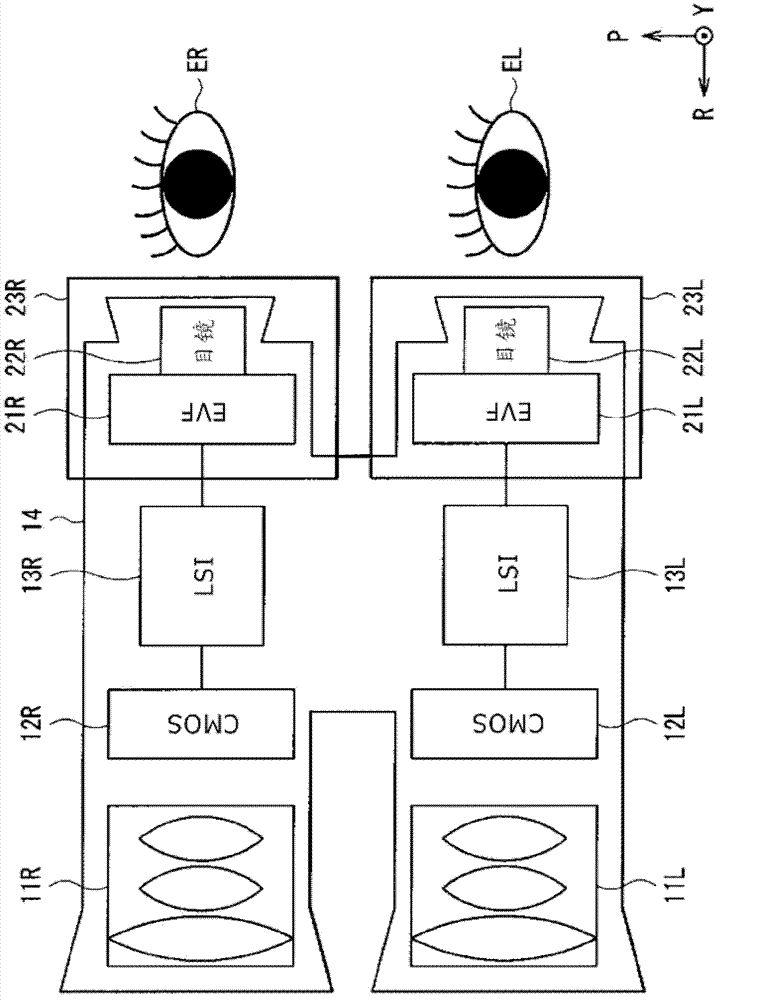
[0040] figure 1 The configuration of an electronic binocular telescope as the imaging device of the first embodiment of the present disclosure is schematically shown. Note that in the drawings, the direction parallel to the width direction (lateral direction or left-right direction) is denoted as P, the direction parallel to the height direction (vertical or up-down direction) is denoted as Y, and the longitudinal direction (front-rear direction) is denoted as R.

[0041] The electronic binoculars are used, for example, when the user views a distant view with his eyes enlarged. An electronic binocular telescope includes, for example, objective lenses 11L and 11R, imaging elements 12L and 12R, large-scale integrated circuits (LSI) 13L and 13R, and electronics from the subject (not shown) side to the user’s left eye EL and right eye ER in order. Viewfinders (EVF) 21L and 21R, and eyepieces 22L and 22R. The objective lenses 11L and 11R, the imaging elements 12L and 12R, and the la...

no. 2 example

[0094] Figure 21 The appearance of a head-mounted display as the display device of the second embodiment of the present disclosure is shown. This head-mounted display has, for example, ear hooks 72 for mounting on the user's head on both sides of the display portion 71 in the shape of glasses.

[0095] Figure 22 show Figure 21 The configuration of the display portion 71 is shown. The display section 71 includes, for example, bases 30L and 30R, display elements 81L and 81R, and eyepieces 82L and 82R in order from the side away from the user's left eye EL and right eye ER similar to the first embodiment.

[0096] The display elements 81L and 81R generate images based on electrical signals. The display elements 81L, 81R are formed of a liquid crystal display panel, an organic EL (Electro Luminescence) display panel, or the like. The user can observe the images displayed on the display elements 81L, 81R in a state where they are enlarged by the eyepieces 82L, 82R.

[0097] The rota...

no. 3 example

[0102] Figure 23 The configuration of an electronic binocular telescope as an imaging device of the third embodiment of the present disclosure is schematically shown. In this electronic binocular telescope, the imaging elements 12L, 12R are provided with bases 30L, 30R similar to the first embodiment, whereby the roll angle, pitch angle, and deflection angle of the imaging elements 12L, 12R can be adjusted. Except for this, the configuration, action and effect of the electronic binocular telescope are similar to those of the first embodiment.

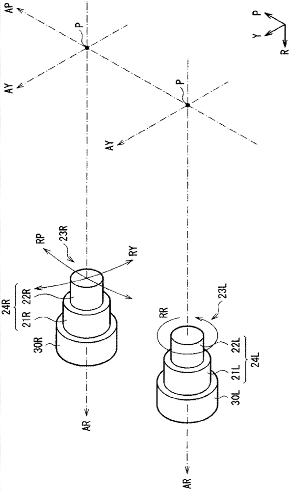
[0103] Specifically, the rotation angle (rolling angle) of the imaging element 12L around the axis AR (longitudinal axis AR) in the longitudinal direction can be adjusted with respect to the imaging element 12R. The electronic binoculars thus allow the roll angle of the imaging elements 12L, 12R to be adjusted.

[0104] In addition, preferably, the rotation angle (pitch angle) of the imaging element 12R about the axis AP (lateral axis AP) ...


PUM


Abstract

The present disclosure provides an imaging device including: a first element for converting image light into an electric signal or generating an image on the basis of an electric signal; and a second element for converting image light into an electric signal or generating an image on the basis of an electric signal, wherein an angle of rotation of the first element about an axis in a longitudinal direction is adjustable with respect to the second element.

Description

Technical field [0001] The present disclosure relates to imaging devices and display devices for users to observe a subject with both eyes, such as binoculars, head-mounted displays, and the like. Background technique [0002] In order for the user to observe the subject with both eyes, the binocular telescope has optical systems respectively corresponding to the left eye and the right eye. In the prior art, the tilt movement of one of the left eyepiece unit and the right eyepiece unit relative to the other eyepiece unit has been proposed as a method for adjusting the optical axes of the left and right optical systems (for example, see Japanese Patent Laid-Open No. 2003-57563). [0003] In an electronic binocular telescope using an electronic viewfinder (Electronic View Finder), light entering from an objective lens is converted into image data by an imaging element such as a CMOS imager, and the image data is displayed on a display element such as a liquid crystal display panel. ...

Claims


Application Information

Patent Timeline
Patent Type & Authority Applications(China)
IPC IPC(8): G02B23/04G02B23/12G02B27/01
CPCG02B2027/0132G02B2027/0154H01L27/14643G02B7/004G02B23/18H04N5/2259H04N5/2252H01L27/14609H04N5/2253H04N23/58H04N23/51H04N23/54
Inventor 冈本绅介
Owner SONY CORP
Learn More