
Rear turning type cash register

A technology of banknote counting machine and turning plate, which is applied in the direction of counting mechanism/articles, instruments, counting objects, etc., can solve the problems of short banknote inspection channels, few sensor installation positions, easy occurrence of banknote jams, etc., and achieves convenient debugging and multi-sensor The effect of the installation location

Inactive Publication Date: 2012-10-17
上海灵岳电子设备有限公司
View PDF4 Cites 6 Cited by
  • Summary
  • Abstract
  • Description
  • Claims
  • Application Information

AI Technical Summary

Problems solved by technology

However, the banknote detection channel of the banknote counting machine of the prior art is relatively short, and the installation positions of sensors are few, and it is more difficult to add sensors
Furthermore, the banknote counter is prone to jamming during the banknote counting process, which requires the banknote counter to be disassembled for maintenance, and the banknote counter needs to be maintained. inconvenient

Method used


Image

  • Rear turning type cash register
  • Rear turning type cash register
  • Rear turning type cash register

Examples


Embodiment Construction

[0028] The present invention will be further described below in conjunction with the accompanying drawings.

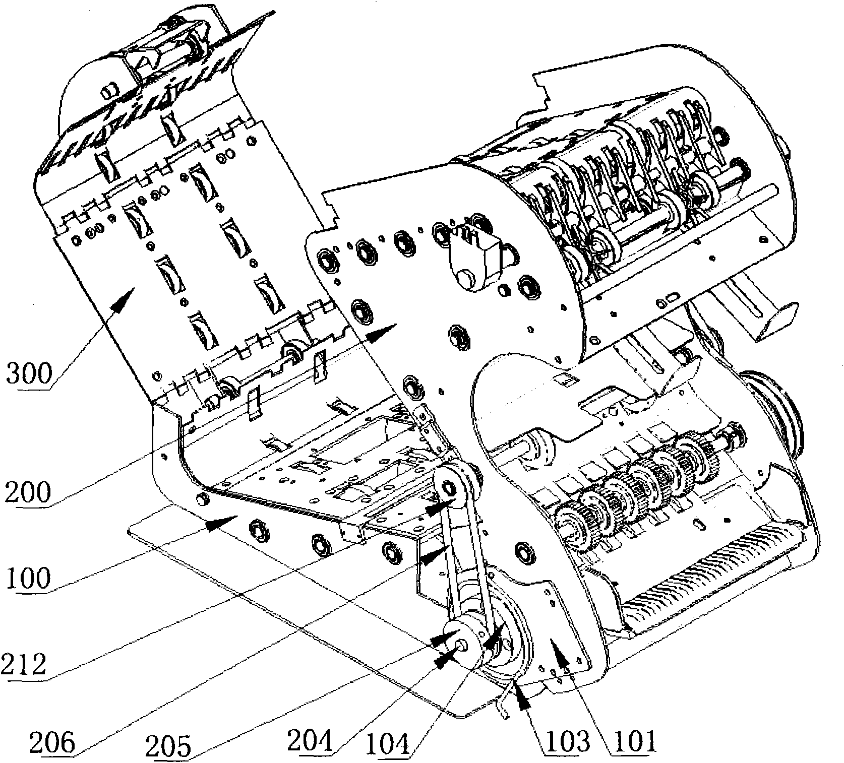
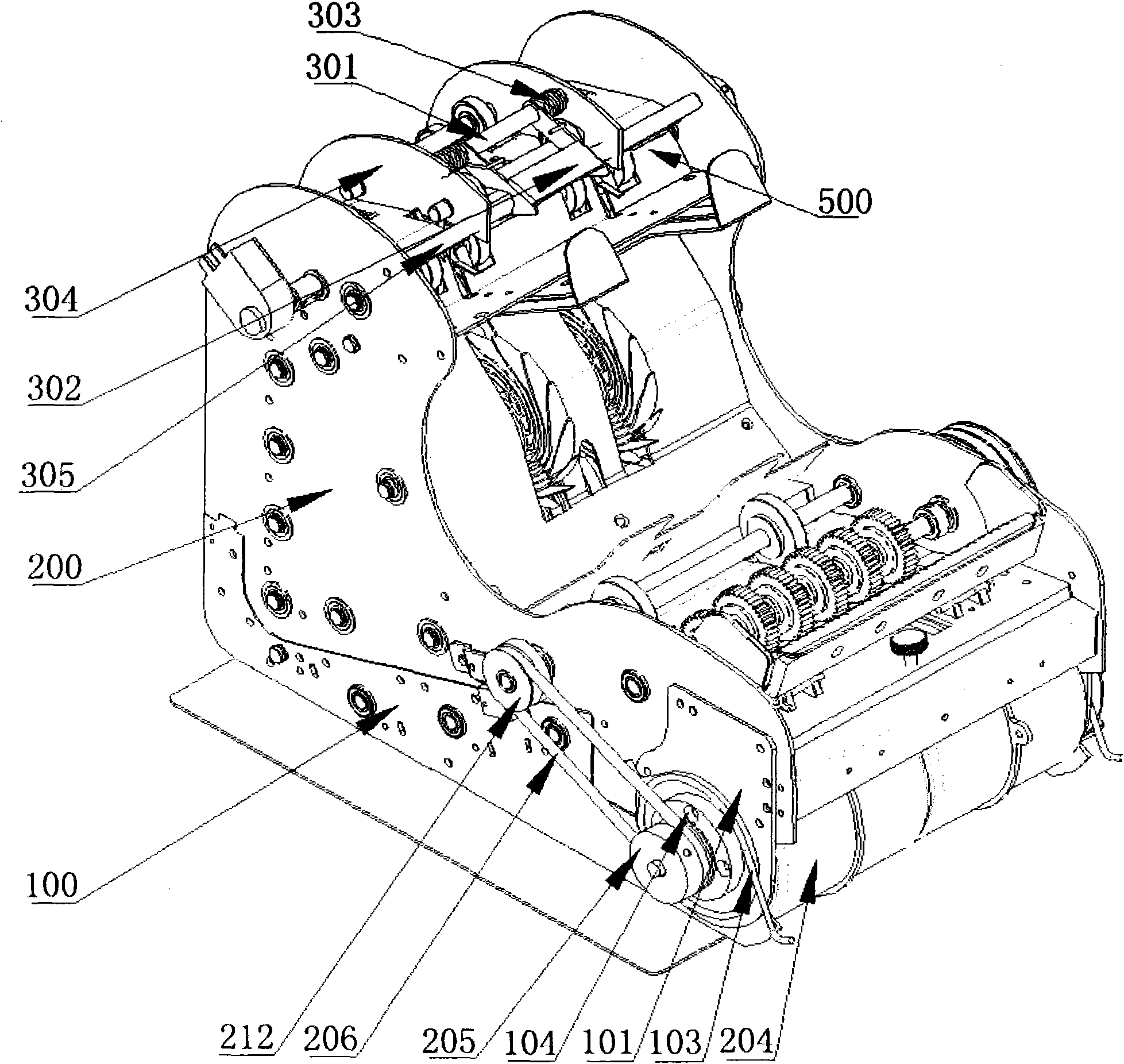
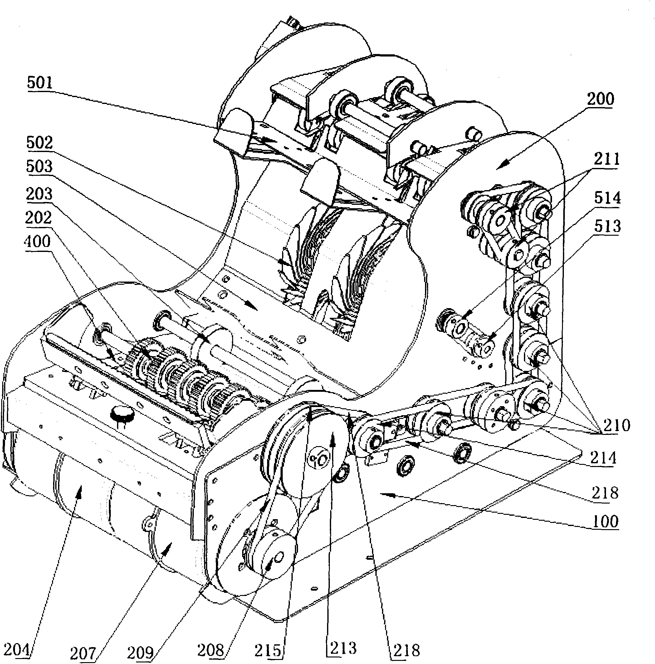
[0029] Such as figure 1 , figure 2 As shown, a rear-turning money counter includes a lower side panel assembly 100, a main side panel assembly 200 and a rear side panel assembly 300, the main side panel assembly 200 is located above the lower side panel assembly 100, and the main side panel assembly 200 The front end of the lower side panel assembly 100 is hinged by a hinge mechanism, the lower side panel assembly 100 and the main side panel assembly 200 form a first transverse banknote transfer channel 600, and the rear side panel assembly 300 is longitudinally arranged on the main side panel assembly 200, the rear side panel assembly 300 is located above the rear end of the lower side panel assembly 100, and the lower end of the rear side panel assembly 300 is hinged to the rear end of the lower side panel assembly 100, and the upper end of the rear side panel asse...


PUM


Abstract

The invention relates to a rear turning type cash register. The rear turning type cash register comprises a lower side plate assembly, a main side plate assembly and a back side plate assembly, wherein the main side plate assembly is above the lower side plate assembly, the main side plate assembly is hinged with the lower side plate assembly, the main side plate assembly and the lower side plate assembly form a first cash passing channel horizontally, the back side plate assembly is at a back of the main side plate assembly, a lower end portion of the back side plate assembly is hinged with a back end portion of the lower side plate assembly, the back side plate assembly and the main side plate assembly are connected by a buckling mechanism, the back side plate assembly and the main side plate assembly form a second cash passing channel vertically, a transmission start port of the first cash passing channel is located at a side region of a cash entrance, a transmission start port of the second cash passing channel is located at a side region of a transmission end port of the first cash passing channel, and a cash exit is at a side region of a transmission end port of the second cash passing channel. According to the invention, the cash passing channels can be opened quite conveniently to enable usage, maintenance and debugging of the cash register more convenient, and moreover the longer cash passing channels have more installation positions for sensors.

Description

technical field [0001] The invention relates to a money counting machine, in particular to a back-turning money counting machine. Background technique [0002] The banknote counter is an electromechanical integrated device that automatically counts the number of banknotes and identifies counterfeit currency. Banknote counters are usually set up in offices with a large amount of cash circulation, and banknote counters have become indispensable equipment. [0003] With the development of the market economy, the requirements for the banknote counterfeiting function of the banknote counter are becoming more and more strict. The banknote detection part of the banknote counter is the core of the whole banknote counter. However, the banknote checking channel of the banknote counter of the prior art is relatively short, and the installation positions of the sensors are few, so it is difficult to add sensors. Furthermore, the banknote counter is prone to jamming during the banknote...

Claims


Application Information

Patent Timeline
Patent Type & Authority Applications(China)
IPC IPC(8): G06M7/06G06M1/00
Inventor 林天祥
Owner 上海灵岳电子设备有限公司
Learn More