LED light source module

A technology of LED light source and LED chip, which is applied in the direction of electrical components, circuits, semiconductor devices, etc., can solve the problems of small light range, complex structure of LED light source module, and unfavorable heat transfer of LED, so as to achieve simple structure and shorten heat transfer Path, the effect of facilitating heat dissipation

Inactive Publication Date: 2012-10-17
东莞怡和佳电子有限公司
View PDF5 Cites 9 Cited by
  • Summary
  • Abstract
  • Description
  • Claims
  • Application Information

AI Technical Summary

Problems solved by technology

This kind of LED light source module has a complex structure, and because the LED light source module 10 has the lead frame 13, it is not conducive to the heat dissipation of the LED.

Method used


Image

  • LED light source module
  • LED light source module
  • LED light source module

Examples


Embodiment Construction

[0009] In order to describe the technical content, structural features, achieved goals and effects of the present invention in detail, the following will be described in detail in conjunction with the embodiments and accompanying drawings.

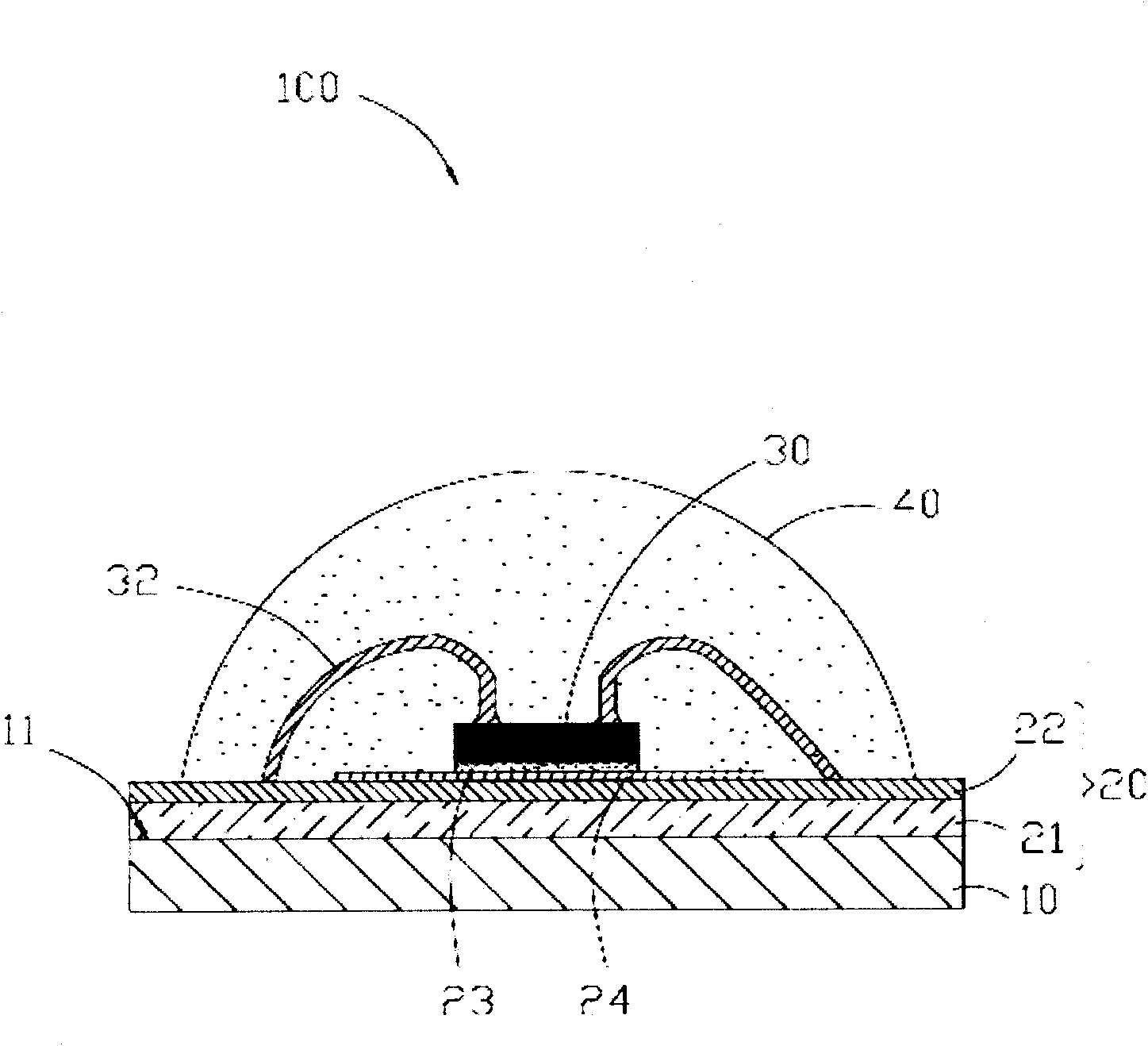
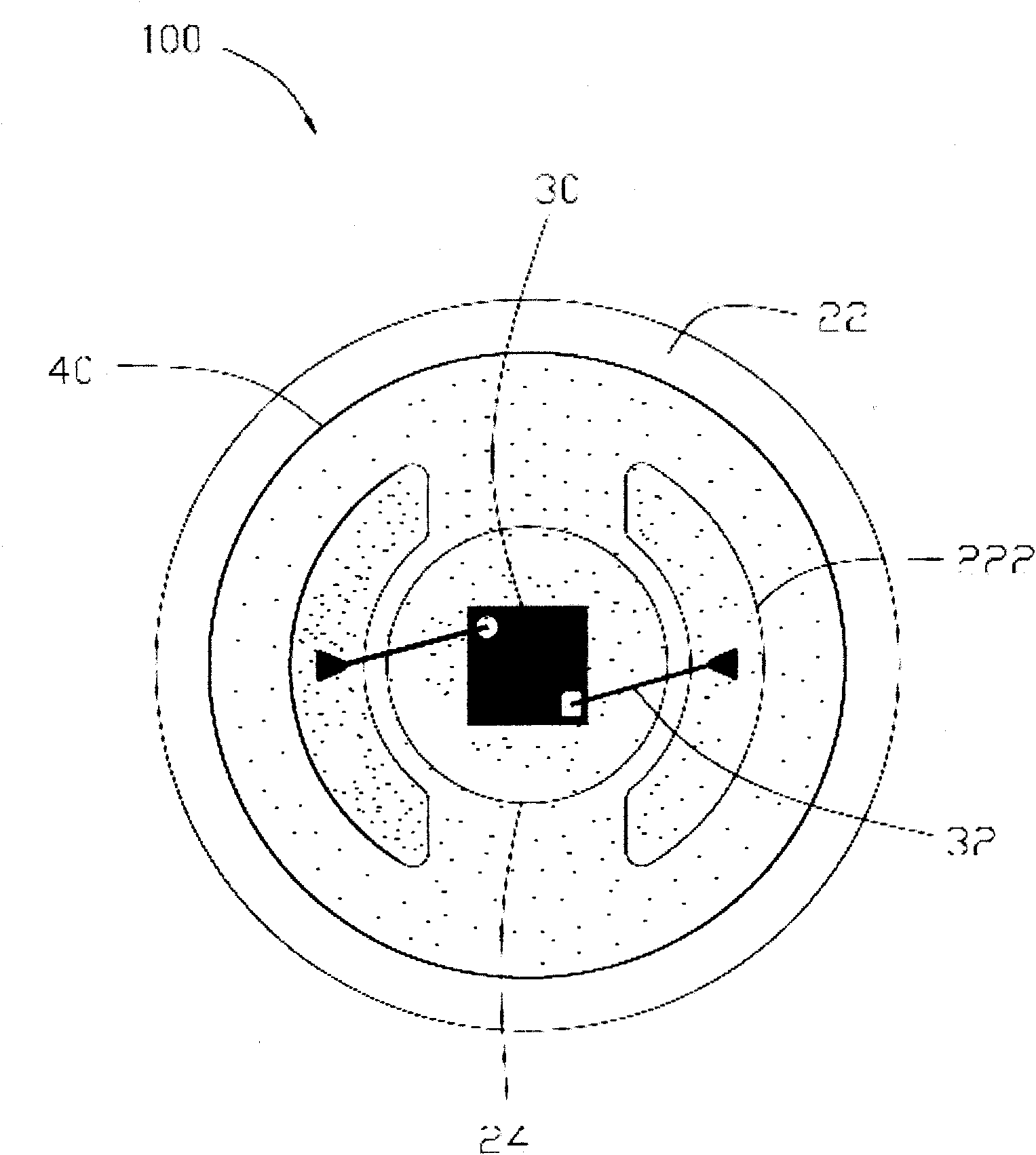
[0010] see figure 1 , the LED light source module 100 of the present invention includes a heat dissipation substrate 10 , a conductive and thermally conductive layer 20 , at least one LED chip 30 , and a plastic package 40 . The conductive and heat-conducting layer 20 is coated on the heat-dissipating substrate 10 , and the plastic package 40 plastic-seals the LED chip 30 on the conductive and heat-conducting layer 20 .

[0011] The heat dissipation substrate 10 is made of materials such as aluminum and silver with good thermal conductivity. In this embodiment, the heat dissipation substrate 10 is an aluminum substrate. The heat dissipation substrate 10 includes a planar upper surface 11 on which the conductive and heat-conducting layer 2...


PUM


Abstract

The invention discloses an LED light source module comprising a heat dissipation substrate, an electrically and thermally conductive layer, at least one LED chip, and a plastic package body. The electrically and thermally conductive layer is coated on the heat dissipation substrate, and the plastic package body seals the LED chip on the electrically and thermally conductive layer. According to the LED light source module, a heat dissipation effect of the LED chip can be improved, and an astigmatism range of light of the LED chip can be enlarged.

Description

technical field [0001] The invention relates to an LED light source module. Background technique [0002] Light-emitting diodes (LEDs) have the advantages of high luminous efficiency, power saving and long life, and their applications are becoming more and more extensive. The LED light source module is formed by packaging the LED through a plastic package. The structure of the existing LED light source module is as follows: figure 1 As shown, an LED light source module 10 includes a heat dissipation substrate 11, a heat conduction plate 12 disposed on the heat dissipation substrate 11, a lead frame 13 disposed on the heat conduction plate 12, and a circuit board disposed in the lead frame 13 14 and an LED chip 15, wherein the LED chip 15 is arranged on the circuit board 14, and a plastic package 16 in which the LED chip 15 is plastic-packed with the lead frame 13. Wherein, the lead frame 13 is roughly in the shape of a round pot, including a bottom plate 131 and a peripher...

Claims


Application Information

Patent Timeline
Patent Type & Authority Applications(China)
IPC IPC(8): H01L33/62H01L33/64H01L33/48
Inventor 汤泽民
Owner 东莞怡和佳电子有限公司
Why Eureka
Try Eureka