
Circuit protection device

A circuit protection and circuit protection technology, applied in overload protection devices, emergency protection circuit devices, electrical components, etc., can solve problems such as failure to work normally, burnout, short circuit of test equipment 100, etc.

Inactive Publication Date: 2012-10-17
SHENXUN COMP KUNSHAN
View PDF5 Cites 4 Cited by
  • Summary
  • Abstract
  • Description
  • Claims
  • Application Information

AI Technical Summary

Problems solved by technology

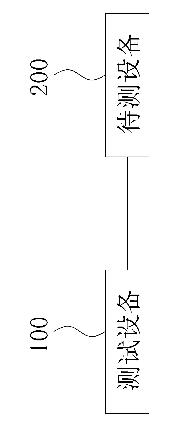
If the circuit of the device under test 200 itself is short-circuited, after the test device 100 is powered, the test device 100 will be short-circuited and cannot work normally or even burn out.

Method used


Image

  • Circuit protection device
  • Circuit protection device
  • Circuit protection device

Examples


Embodiment Construction

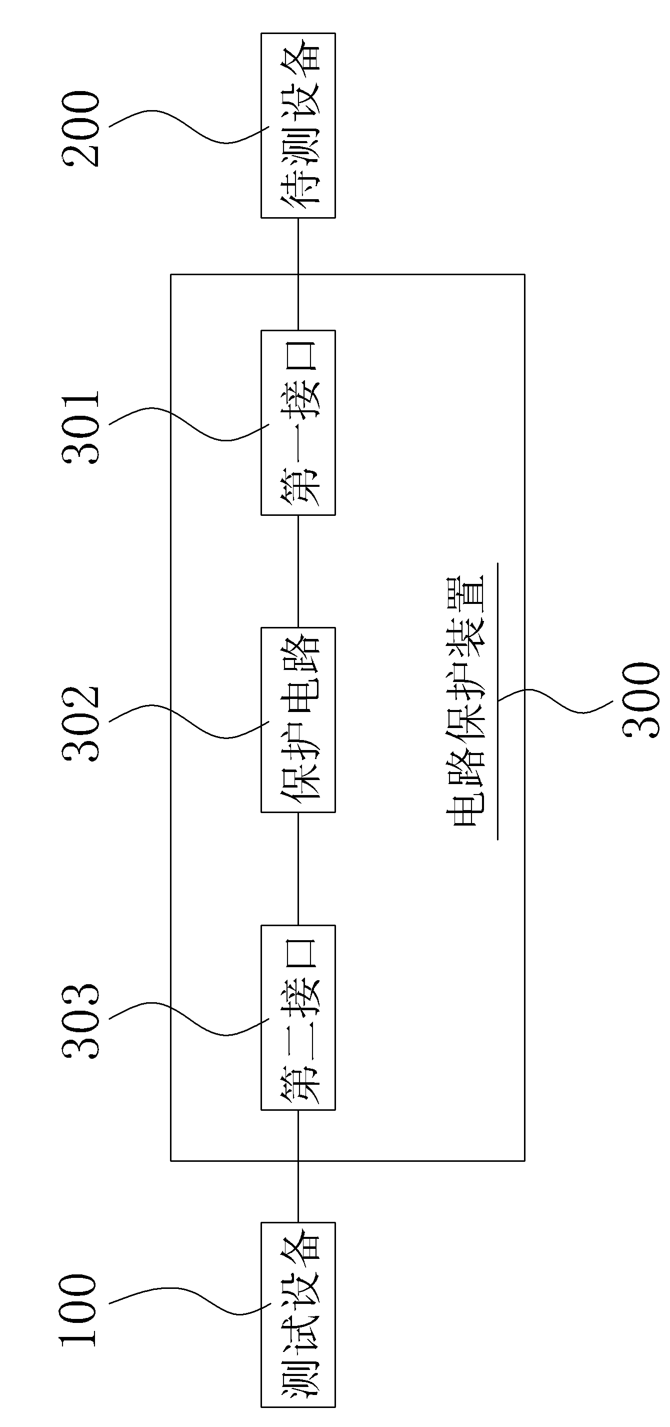
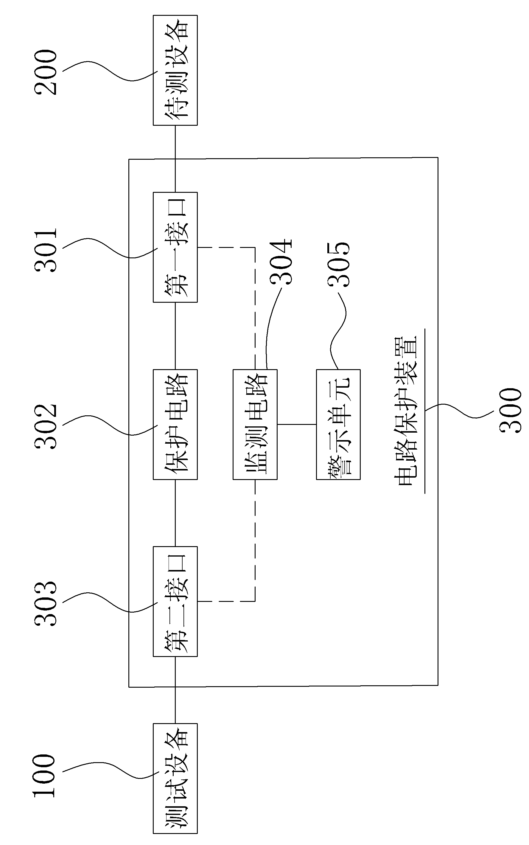
[0025] see figure 2 , figure 2 It is a block structure diagram of the application status of the first embodiment of the circuit protection device of the present invention.

[0026] The circuit protection device 300 provided by the present invention is connected to the test equipment 100 and the equipment under test 200. In the first embodiment, the circuit protection device 300 includes:

[0027] The first interface 301 is electrically connected to the device under test 200 to obtain a first level state;

[0028] A protection circuit 302, one end of which is electrically connected to the first interface 301, acquires the first level state, and controls the on-off of the protection circuit 302 according to the first level state;

[0029] One end of the second interface 303 is electrically connected to the other end of the protection circuit 302 , and the other end is electrically connected to the testing device 100 .

[0030] Here, the protection circuit 302 may include a ...


PUM


Abstract

The invention discloses a circuit protection device which is connected with a test device and a device under test. The circuit protection device comprises a first interface which is electrically connected with the device under test, wherein a first level state is acquired; a protection circuit with one end thereof electrically connected with the first interface, wherein the first level state is acquired and the on / off state of the protection circuit is controlled according to the first level state; and a second interface with one end thereof electrically connected with the other end of the protection circuit, and the other end of second interface electrically connected with the test device. By using the circuit protection device, the first level state of the device under test is acquired through the first interface and the on / off state of the protection circuit is controlled according to the first level state. Therefore the protection for the test device is obtained.

Description

【Technical field】 [0001] The invention relates to a circuit protection device, in particular to a circuit protection device for testing equipment. 【Background technique】 [0002] With the development and progress of science and technology, electronic products are more and more widely used in home and office occasions, especially personal desktop computers and notebook computers, which have become an indispensable tool in people's life. [0003] Therefore, mass production of such electronic products is required. Before the factory needs to ship, its performance needs to be tested to ensure its quality. [0004] see figure 1 , which is shown as a test structure diagram of an electronic product in the prior art. In current tests, the testing device 100 is usually electrically connected to the device under test 200 directly. [0005] The device under test 200 is an example of a notebook computer display, and the testing device 100 is an example of a notebook computer host. ...

Claims


Application Information

Patent Timeline
Patent Type & Authority Applications(China)
IPC IPC(8): H02H7/00G01R1/36
Inventor 任光明
Owner SHENXUN COMP KUNSHAN
Learn More