Radio heavy fog weather monitoring method and system, computer equipment and medium
A radio and radio signal technology, applied in the field of electronic information, can solve the problems of difficult maintenance, high installation cost, fixed-point measurement, etc., and achieve high spatial and temporal resolution, low cost, and simple reception
- Summary
- Abstract
- Description
- Claims
- Application Information
AI Technical Summary
Problems solved by technology
Method used
Image
Examples
Embodiment 1
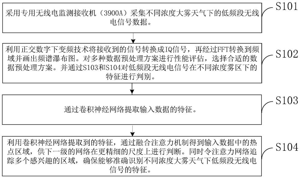
[0061] like figure 1 Show, the monitoring method of radio heavy fog weather based on deep learning provided by the invention embodiment includes the following steps:
[0062] S101 uses a dedicated radio monitoring receiver (3900A) to collect low -frequency band radio signal data in different concentrations of fog.
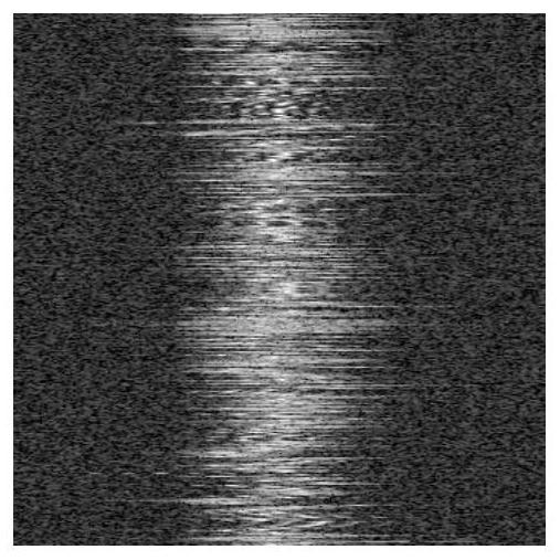
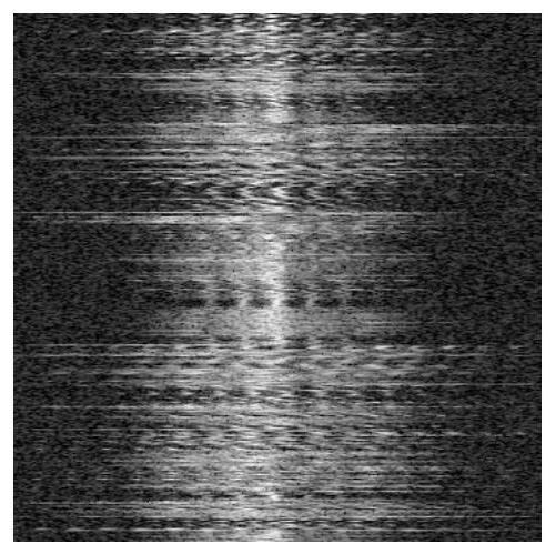
[0063] S102, uses the orthogonal digital inverter technology to convert the received signal to IQ signal, and then convert it to FFT to the frequency domain and draw the spectrum waterfall map. Perform performance evaluation of multiple data pre -processing schemes, and select the appropriate data pre -processing scheme. And the characteristics of the low -frequency band radio signal in different concentrations through the S103 and S104 are discriminated.
[0064] S103 extracts the characteristics of input data through convolutional neural networks.
[0065] S104, using the characteristics of withdrawal of convolutional neural networks to obtain hotspots in the input d...
Embodiment 2
[0077] Based on embodiment 1 based on deep learning -based radio motion monitoring methods, as preferred embodiment, in step S101, the low -frequency band radio signal is the low -frequency band baseband signal of the receiving frequency band. Continuously change the position of the receiver in the fog area to exclude the effects of the same channel on the characteristics of the fog of wireless telecommunications.
Embodiment 3
[0079] Based on embodiment 1 based on deep learning -based radio and fog weather monitoring methods, as preferred embodiments, in step S102, the use of orthogonal digital inverter technology will be converted to IQ signals. The
[0080] I = h LP (s (t) cos (2πft))
[0081] Q = h LP (s (t) sin (2πft))
[0082] Among them, s (t) is the receiving signal, F represents the carrier frequency of the transmission signal, H LP Represents the system function of a low -pass filter.
PUM
 Abstract
Description
Claims
Application Information
 - R&D
- Intellectual Property
- Life Sciences
- Materials
- Tech Scout
- Unparalleled Data Quality
- Higher Quality Content
- 60% Fewer Hallucinations
Browse by: Latest US Patents, China's latest patents, Technical Efficacy Thesaurus, Application Domain, Technology Topic, Popular Technical Reports.
© 2025 PatSnap. All rights reserved.Legal|Privacy policy|Modern Slavery Act Transparency Statement|Sitemap|About US| Contact US: help@patsnap.com


