Battery loading vehicle

A technology for battery loading and loading vehicles, applied in the directions of transportation, packaging, roller tracks, etc., can solve the problems of increasing battery safety, lack of transplanting vehicles and equipment, and cumbersome operation, so as to improve transfer safety, ensure mobile safety, The effect of preventing tipping

Inactive Publication Date: 2014-12-17
HUNAN GEELY AUTOMOBILE COMPONENTS +1
View PDF8 Cites 0 Cited by
  • Summary
  • Abstract
  • Description
  • Claims
  • Application Information

AI Technical Summary

Problems solved by technology

[0005] The invention solves the disadvantages in the prior art that a forklift or a crane is required to transfer the storage battery from the equipment to the charging position, which is cumbersome to operate and troublesome to use, and provides a battery loading vehicle that can directly transfer the storage battery from the equipment to the charging position on the ground, which is convenient to use
[0007] The present invention also solves the defect that there is no transition part between the transplanting vehicle and the equipment in the prior art, and the storage battery is easy to fall to the ground and be damaged during the process of moving out of the equipment. components to increase safety during battery transfer

Method used


Image

  • Battery loading vehicle
  • Battery loading vehicle
  • Battery loading vehicle

Examples


Embodiment 1

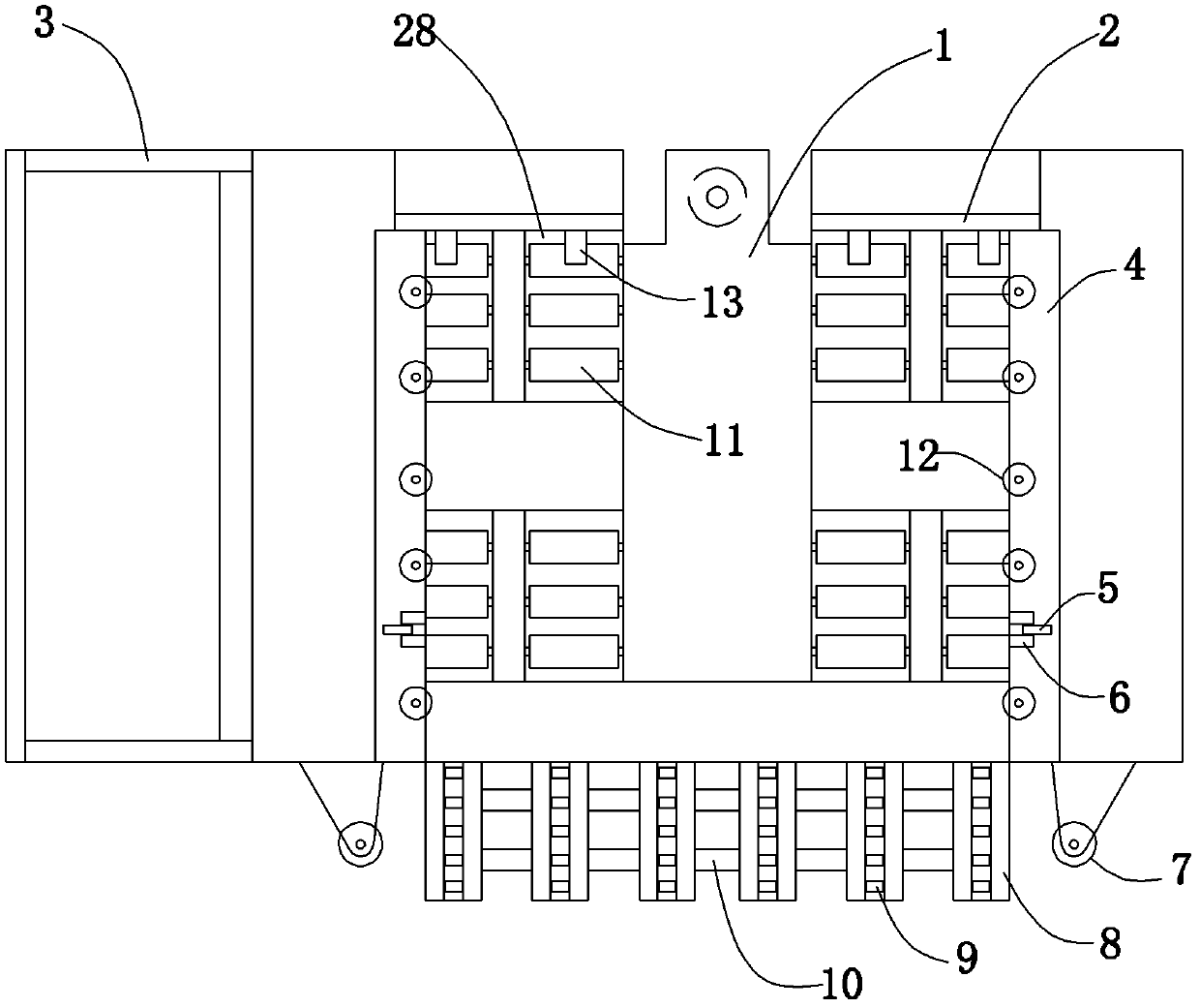
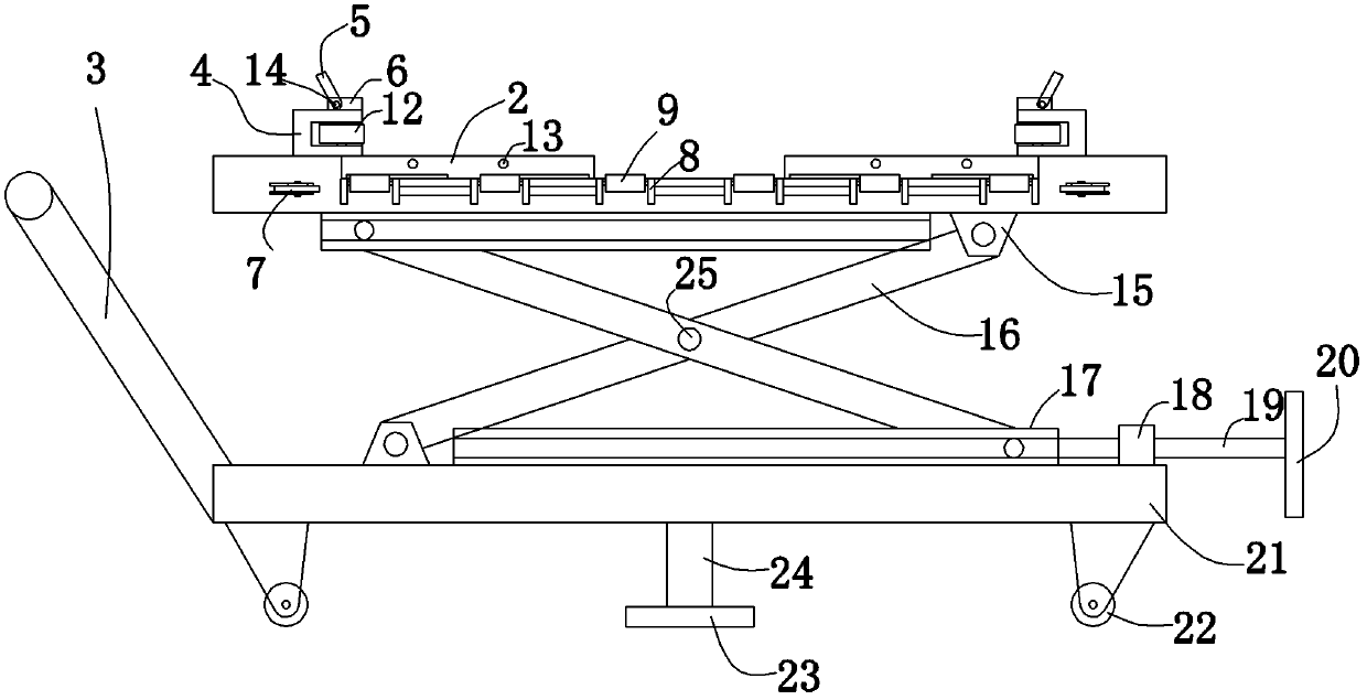
[0025] Embodiment 1: a battery loading vehicle (see attached figure 1 attached figure 2 ), the frame of the loading vehicle includes a lifting frame and a bearing platform 1 arranged above the lifting frame, and four traveling wheels 22 are arranged at the bottom of the lifting frame.

[0026]The elevating frame comprises a frame bottom 21, two groups of frame bodies 16 hinged in an X shape through hinge shafts 25 arranged on the frame bottom, and a drive mechanism that drives the frame body to rotate around the hinged position. There are four walking wheels arranged on the bottom surface of the frame. An inclined handle 3 is fixed on the side of the frame bottom. Two hinge seats 15 and two slide rails 17 are fixed on the chassis, and the slide rails are C-shaped, and the C-shaped openings of the two slide rails are opposite. Two of the frame bodies are quadrangular in total, one is a small frame body, and the other is a large frame body, and the maximum width of the small...

Embodiment 2

[0030] Embodiment 2: A battery loading vehicle, the bridging portion is fixed to the side of the carrying platform, the upper plane formed by the second rollers on the bridging frame is inclined to the upper plane formed by the first rollers, and the second rollers are formed The edge of the upper plane near the side of the loading vehicle is abutted with the edge of the upper plane formed by the first roller near the side of the loading vehicle. Refer to Example 1 for all the other structures.

Embodiment 3

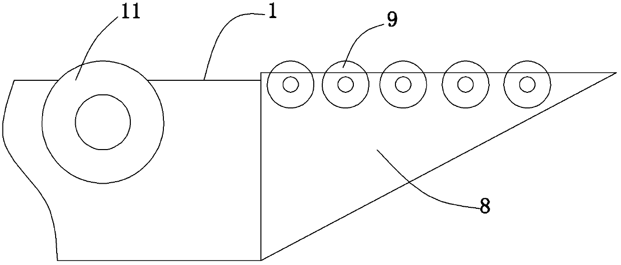
[0031] Embodiment 3: a battery loading vehicle (see attached Figure 4 ), the side of the bearing platform is fixed with a support 26, and the beam of the bridging part is hinged to the support through the rotating shaft 27, the beam body is rectangular, and the end of the beam is a triangular structure. Refer to Example 1 for all the other structures.

[0032] Transfer the loading vehicle to the equipment with battery replacement, turn the handle 20, raise the load-carrying platform, and after rising to a suitable height, connect the end of the bridging part to the opening of the battery installation part, and the side anti-collision wheel Hold the side of the device, adjust the position, and then rotate the stud, the brake disc is against the ground. Pull the storage battery out from the equipment and transfer it to the carrying platform close to the limit column 13, then turn over the limit block 5 to block the storage battery. Then loosen the studs, raise the brake disc,...


PUM


Abstract

The invention relates to a battery loading vehicle and solves the problem that a storage battery is easy to fall on the ground and be damaged while moved out of equipment in the prior art. The battery loading vehicle comprises a vehicle frame, a plurality of walking wheels are arranged at the bottom of the vehicle frame, a loading platform is arranged on the upper portion of the vehicle frame, a first roller is pivoted on the bearing platform, and a supporting plane composed of the first roller protrudes to the bearing platform; a block portion is arranged on the bearing platform; a bridging portion is connected to a lateral side of the loading vehicle parallel with the axis of the roller, and the bridging portion comprises a bridging frame and a second roller arranged on the bridging frame and protruding out of the upper surface of the bridging frame. The bridging portion serves as a bridge between the bearing platform and the mounting position of an equipment storage battery, and plays of a supporting role during the transferring process of the storage battery, the storage battery is prevented from turning over, and the transferring safety is improved.

Description

technical field [0001] The invention relates to a carrying tool, in particular to a battery loading vehicle which is convenient for carrying batteries and reduces the labor intensity of workers. Background technique [0002] In the production process, the batteries of many large-scale equipment are used frequently, and the power consumption is large. The batteries often need to be moved for charging due to insufficient power. Since the batteries and other items that need to be moved are heavy and cannot be transported by workers, they generally need to use forklifts or Crane operation, transfer the heavy battery to a proper location for charging, and then transfer the charged battery to the equipment for assembly and use. The whole operation is cumbersome and inconvenient, requiring a lot of manpower. After the battery is removed from the equipment, there is no standard station equipment for charging operations, which will affect the 5S status on site, and there are also maj...

Claims


Application Information

Patent Timeline
Patent Type & Authority Patents(China)
IPC IPC(8): B65G13/12
Inventor 张旭霖赵桢胡边疆罗显任
Owner HUNAN GEELY AUTOMOBILE COMPONENTS
Why Eureka
Try Eureka