
Thin heat exchange type air interchanger

A technology of ventilation device and heat exchanger, which is applied in the field of heat exchange type ventilation device and thin heat exchange type ventilation device, which can solve the problems of low heat exchange efficiency, small size and thinness, etc., and achieve the goal of exchanging The gas device is compact, the power consumption is increased, and the effect of small volume

Active Publication Date: 2015-06-10
北京环都拓普空调有限公司
View PDF9 Cites 0 Cited by
  • Summary
  • Abstract
  • Description
  • Claims
  • Application Information

AI Technical Summary

Problems solved by technology

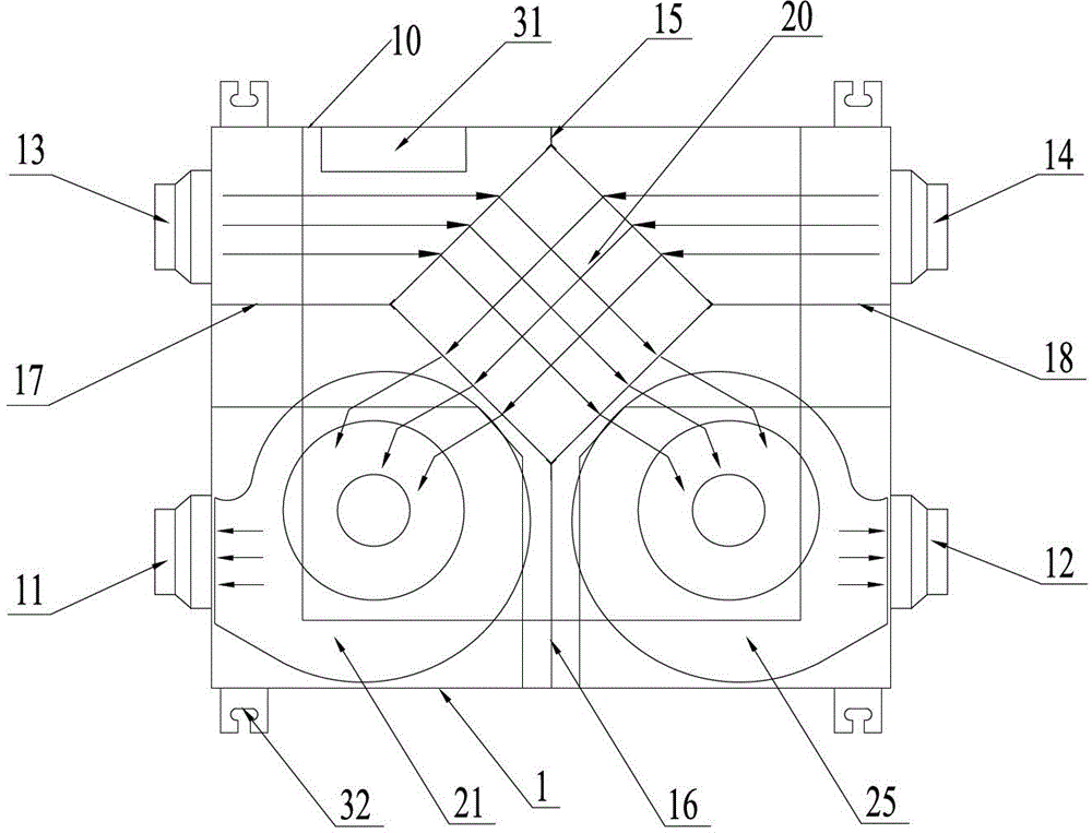
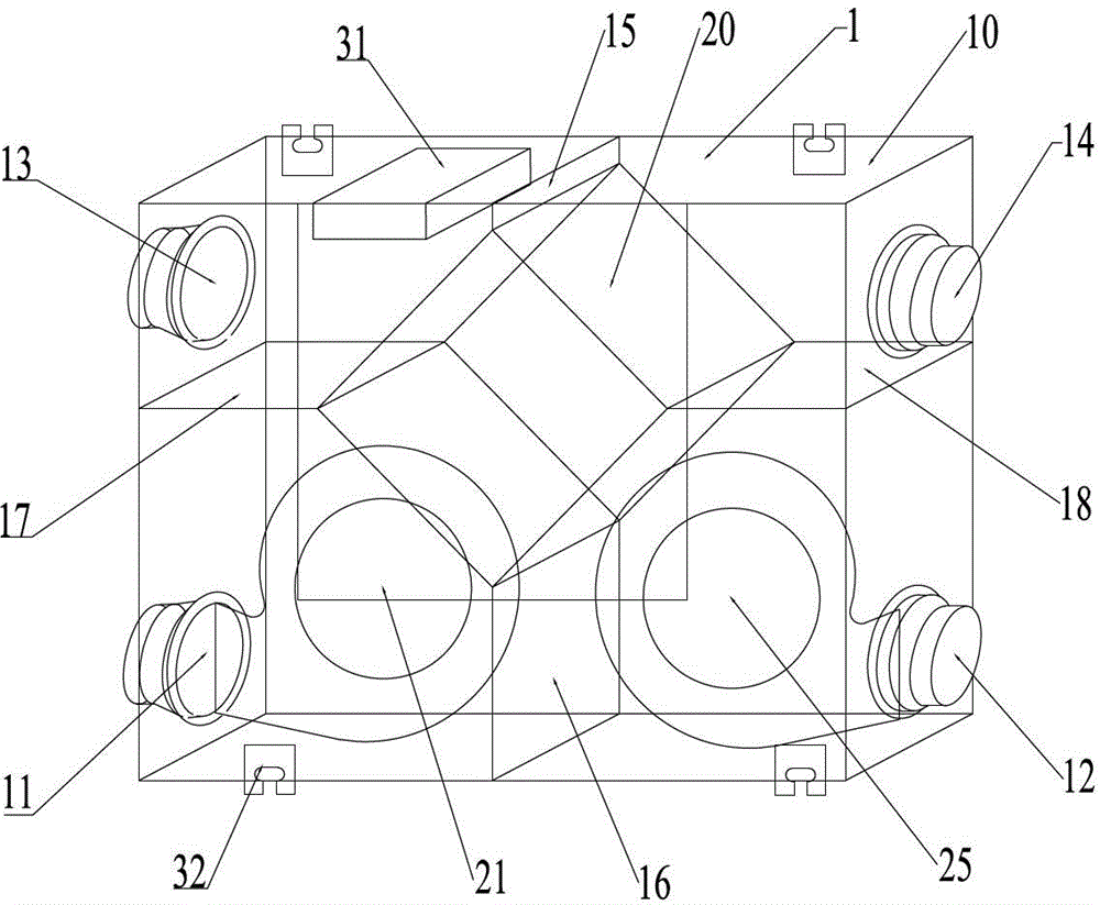
[0004] There are some existing designs that use a diagonal exchange method, but because of the use of vertical fans, it is impossible to achieve small size and thinness
[0005] There are also some existing designs that adopt different heat exchangers, resulting in low heat exchange efficiency with the same volume of the present invention

Method used


Image

  • Thin heat exchange type air interchanger
  • Thin heat exchange type air interchanger
  • Thin heat exchange type air interchanger

Examples


no. 2 example

[0069] Such as Figure 9 As shown, the shape of the heat exchanger of the second embodiment can be changed to a hexagonal shape, which can reduce the volume of the equipment, and will be smaller than the volume of the ventilation device of the first embodiment. Only the parts different from the first embodiment will be described here.

[0070] Specific as Figure 9 As shown, the hexagonal heat exchanger has short sides 35 located at two upper and lower positions, and four long sides 36 respectively connected to the short sides. A connection plate 37 connecting the heat exchanger and the side wall is formed between the two long sides. The long side 36 at the bottom, the short side 35 at the bottom, the connecting plate 37, the side wall 10 and the lower air channel plate 16 isolate the fresh air supply space or the return air discharge space for accommodating the blower or exhaust fan.

[0071] The long side 36 located below, that is, the long side 36 close to the air blower...

no. 3 example

[0075] Such as Figure 10 As shown, the shapes of the two air inlet surfaces and the two air outlet surfaces of the heat exchanger of the third embodiment can be changed into four circular arcs, which can reduce the volume of the equipment, and it will be smaller than that of the first embodiment. The ventilator is smaller in size. Only the parts different from the first embodiment will be described here.

[0076] The heat exchanger 3 in this embodiment has four arc sides 38 and three straight sides 39 connecting the arc sides 38 and the side wall 10 . The radius R of the arc edge 38 corresponds to the radius r of the air blower or the exhaust fan, so as to ensure that the distance M between the volute of the wind wheel and the air outlet surface of the heat exchanger is an appropriate size, that is, R=r+M.

[0077] In this example, the Figure 10 The upper middle arc edge 38 (that is, the arc edge located between the fresh air outlet and the return air outlet) is directly ...


PUM


Abstract

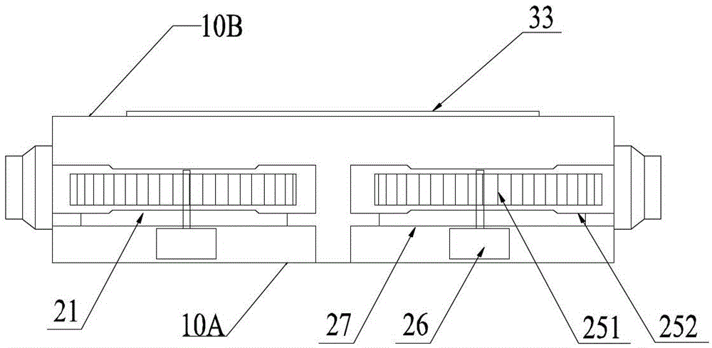
The invention discloses a thin heat exchange type air interchanger which increases small power dissipation. The thin heat exchange type air interchanger comprises a machine casing, a heat exchange machine, a blower and an exhaust fan, wherein the heat exchange machine, the blower and the exhaust fan are built in the machine casing, a wind return port and a wind supplying port are arranged on an indoor side on the lateral wall of the machine casing, a new wind port and a wind exhaust port are arranged on the outdoor side of the lateral wall of the machine casing, the blower is arranged between the heat exchange machine and the wind supplying port, the exhaust fan is arranged between the heat exchange machine and the wind exhaust port, and the blower and the exhaust fan are arranged on the same side of the lateral wall. The thin heat exchange type air interchanger is compact in structure, achieves thin shapes and miniaturization, can occupy small suspended ceiling area, and can achieve small size under the condition of same heat exchange efficiency.

Description

technical field [0001] The invention relates to a heat exchange type ventilator, in particular to a thin heat exchange type ventilator, which belongs to the technical field of air conditioning. Background technique [0002] During decoration, the air exchange device is horizontally installed between the roof and the ceiling at the top of the house, and the height of the air exchange device is an important factor determining the height of the suspended ceiling of the house. With the requirement of the height of housing now, the height of ventilation device is also getting smaller and smaller. In order to meet the needs of decoration, the ventilation device is also becoming more and more miniaturized, so as to reduce the occupied ceiling area. [0003] The exchange of cold and hot air in the previous design of similar products is a linear exchange method, so that the inlet of cold and hot air must be set at both ends of the movement, and the fan must be set at the other two e...

Claims


Application Information

Patent Timeline
Patent Type & Authority Patents(China)
IPC IPC(8): F24F7/08F24F12/00F24F13/30
Inventor 孟东辉张海龙
Owner 北京环都拓普空调有限公司
Learn More