Capacitor detection method and capacitor detection circuit

A capacitance detection and capacitance technology, applied in the field of electronics, can solve the problem that the capacitance to be detected cannot be effectively detected, and achieve the effect of strong adaptability and versatility

Active Publication Date: 2012-10-24
CHIPSEMI SEMICON (NINGBO) CO LTD
View PDF13 Cites 13 Cited by
  • Summary
  • Abstract
  • Description
  • Claims
  • Application Information

AI Technical Summary

Problems solved by technology

[0009] The purpose of the present invention is to provide a capacitance detection method and a capacitance detection circuit to solve the contradiction that the capacitance value of the capacitance to be detected

Method used


Image

  • Capacitor detection method and capacitor detection circuit
  • Capacitor detection method and capacitor detection circuit
  • Capacitor detection method and capacitor detection circuit

Examples


Embodiment Construction

[0037] In order to make the objectives, technical solutions, and advantages of the present invention clearer, the various embodiments of the present invention will be described in detail below with reference to the accompanying drawings. However, a person of ordinary skill in the art can understand that, in each embodiment of the present invention, many technical details are proposed for the reader to better understand the present application. However, even without these technical details and various changes and modifications based on the following embodiments, the technical solutions claimed by the claims of this application can be realized.

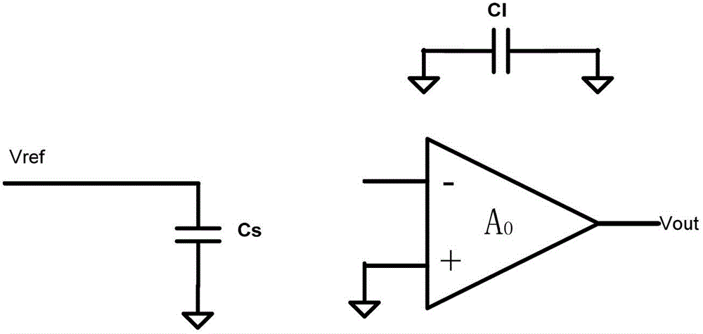
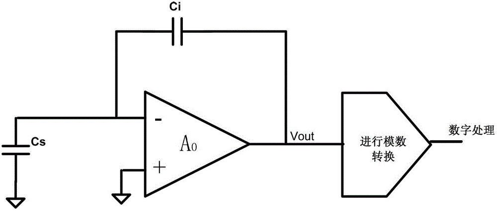
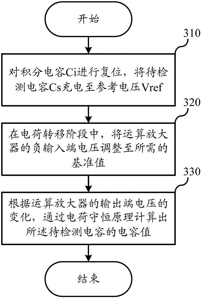
[0038] The first embodiment of the present invention relates to a capacitance detection method. The specific process is as image 3 Shown.

[0039] In step 310, the integrating capacitor Ci is reset, and the capacitor Cs to be detected is charged to the reference voltage Vref. This step is the sampling phase in the capacitance detection pro...


PUM


Abstract

The invention relates to the field of electronics, and discloses a capacitor detection method and a capacitor detection circuit. According to the method, the voltage of a negative input end of an operational amplifier is adjusted to the required reference value, and the voltage of the upper end of a capacitor Cs to be detected can be limited to Vset in the charge transfer phase, i.e. the charge on a sampling capacitor Cs is not completely transferred onto an integrating capacitor Ci. Consequently, the charge conservation principle can also be utilized, and according to the voltage variation of the output end of the operational amplifier, the capacitance of the capacitor to be detected is calculated. Because the voltage of the negative input end of the operational amplifier is adjustable, even if the capacitor with the capacitance varies from a small miicromicro farad to hundreds of miicromicro farads is detected, the voltage of the output end of the operational amplifier can still be controlled within a reasonable scope through adjusting the voltage of the negative input end of the operational amplifier, and accordingly, the capacitor detection method is enabled to detect the capacitor with the capacitance which varies from a small miicromicro farad to hundreds of miicromicro farads.

Description

Technical field [0001] The present invention relates to the field of electronics, in particular to capacitance detection in capacitive touch or capacitive buttons. Background technique [0002] At present, capacitive touch technology has developed rapidly and brought great convenience to people’s lives. The technology first divides the touch detection area into a number of grid points that intersect horizontally and vertically, and then detects the change in the capacitance value of the grid point to obtain the touch point Location information. [0003] If the capacitive touch technology is classified according to the specific implementation, it includes capacitive buttons, self-sensing capacitive screens, and mutual-sensing capacitive screens. Among them, capacitive buttons and self-sensing capacitive screens have a large range of capacitance to be measured, and some small touch circuit boards Among them, the self-inductance capacitance value is only a few picofarads, while in so...

Claims


Application Information

Patent Timeline
IPC IPC(8): G01R27/26
Inventor 谢循张耀国方飞王广
Owner CHIPSEMI SEMICON (NINGBO) CO LTD
Why Eureka
Try Eureka