Supercharge Your Innovation With Domain-Expert AI Agents!

Methods for wireless communication system

A wireless communication system and radio resource control technology, applied in diversity/multi-antenna systems, space transmit diversity, etc., to achieve enhanced capacity and improved channel evaluation performance

Inactive Publication Date: 2012-10-24
HUAWEI TECH CO LTD
View PDF4 Cites 7 Cited by
  • Summary
  • Abstract
  • Description
  • Claims
  • Application Information

AI Technical Summary

Problems solved by technology

Therefore, there is no set of reference signals that need to be shared among users in the system

Method used


Image

  • Methods for wireless communication system
  • Methods for wireless communication system
  • Methods for wireless communication system

Examples


Embodiment Construction

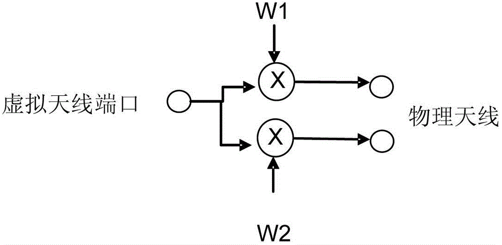
[0026] A user terminal may have multiple physical antennas. If the same signal is transmitted from multiple physical antennas at the same time, these physical antennas can be jointly considered as a large virtual antenna consisting of multiple physical antennas that is logically / electronically one. From the perspective of the receiver, the physical antennas are transparent, which means that they cannot be distinguished independently. The concept of virtual antennas is still valid if each physical antenna is multiplied by a complex-valued constant. In this case, the virtual antenna is obtained by a linear mapping from the virtual antenna port (or equivalently the virtual antenna input) to the physical antenna. Regardless of what is being emitted from the virtual antenna, there will be a defined mapping and emission from the physical antenna. image 3 An example of mapping of one virtual antenna port to two physical antennas is shown.

[0027] The mapping is usually described...


PUM


Abstract

The invention relates to a method of a central node (CN) and a method of a remote node (RN) which are applied to reference signal distribution of uplink transmission in a wireless communication system. According to one respect of the methods, one method is used for the distribution of a reference signal, the method includes the following steps that the number N of reference signals of the uplink transmission is determined in the CN, the reference signals of the uplink transmission are used by the RN, the number N of the reference signals which are used by the RN for an uplink is indicated to the RN, the uplink transmission is configured by a maximum number N of the reference signals which are used by the RN, the uplink transmission of the maximum number N of the reference signals on a sending antenna is performed, and the reference signals on the sending antenna are executed by the RN and contained in the RN. The CN and the RN which are related to the methods are further disclosed.

Description

technical field [0001] The present invention relates to a method in a central node, a method in a remote node, and a method in a wireless communication system for allocating reference signals for uplink transmission in a wireless communication system, and also discloses central node and remote remote node. Background technique [0002] A mobile workstation (MS) may have multiple physical antennas, and each physical antenna has a corresponding transmit power amplifier. A measurement reference signal Sounding Reference Signal (SRS) is transmitted from each physical antenna for measurement at the receiving base station (BS). The SRSs from different antennas can be code-multiplexed, frequency-multiplexed or time-multiplexed. In addition, the SRSs of all users in the cell need to be multiplexed. SRS resources are allocated to different MSs in a semi-static mode by high-level signaling from BS to MSs. [0003] Furthermore, in order to coherently demodulate the transmitted signa...

Claims


Application Information

Patent Timeline
IPC IPC(8): H04B7/04
Inventor 马蒂尔斯・温斯特姆刘江华布兰尼斯拉夫・波波维奇
Owner HUAWEI TECH CO LTD
Features
  • R&D
  • Intellectual Property
  • Life Sciences
  • Materials
  • Tech Scout
  • Unparalleled Data Quality
  • Higher Quality Content
  • 60% Fewer Hallucinations
Learn More