Cutting tool

A cutting tool and sipe technology, which is applied in the field of cutting tools, can solve the problems of sawtooth structure deformation, high processing difficulty, and damage to the tool, and achieve the effects of easy processing and production, low production cost, and improved stability

Active Publication Date: 2012-10-31
ZHUZHOU CEMENTED CARBIDE CUTTING TOOLS CO LTD
View PDF8 Cites 2 Cited by
  • Summary
  • Abstract
  • Description
  • Claims
  • Application Information

AI Technical Summary

Problems solved by technology

Although this structure can effectively prevent the blade from flying out during the cutting process, it is relatively complicated in shape, cumbersome to manufacture and difficult to process. Too many teeth require higher manufacturing precision to ensure the tooth profile of the cutting blade and the sipe teeth The shape and surface fit se

Method used


Image

  • Cutting tool
  • Cutting tool
  • Cutting tool

Examples


Embodiment Construction

[0016] The present invention will be further described in detail below in conjunction with the drawings and specific embodiments.

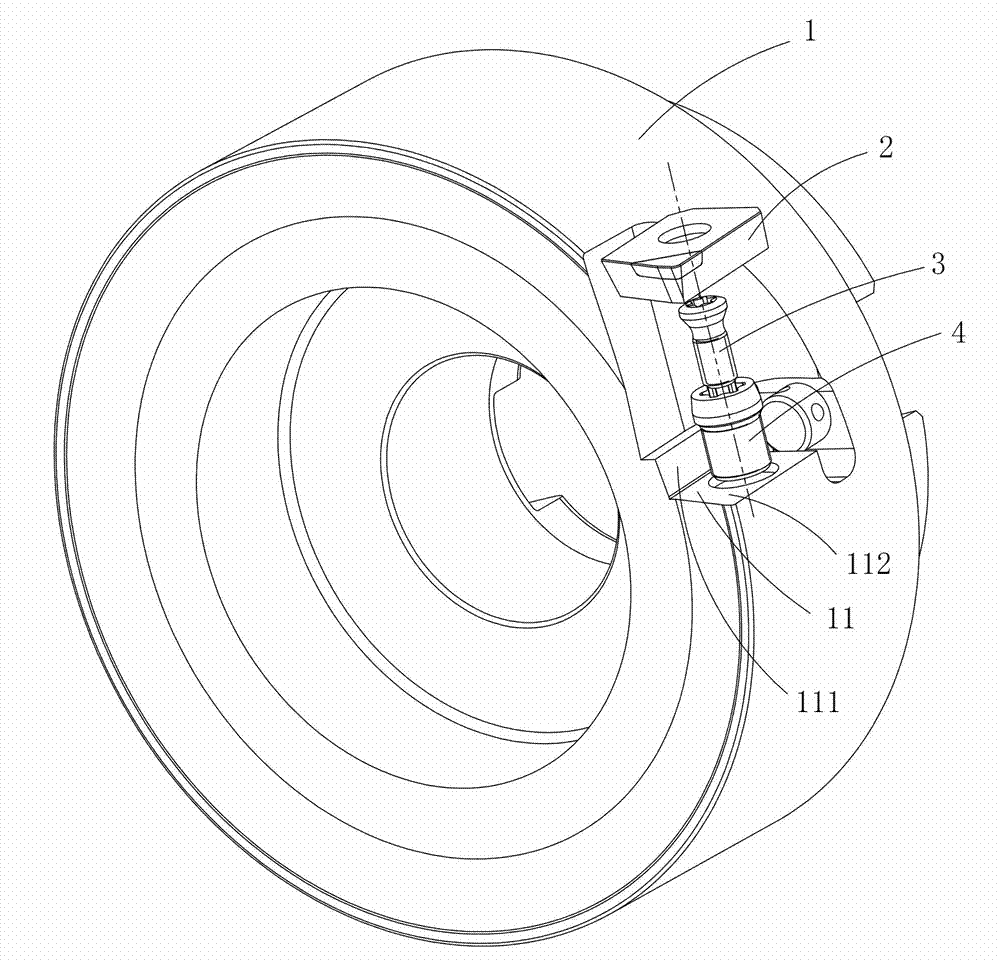
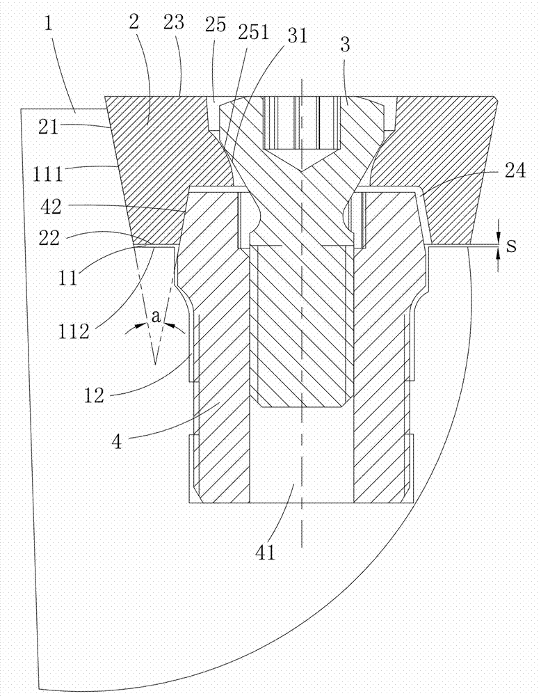
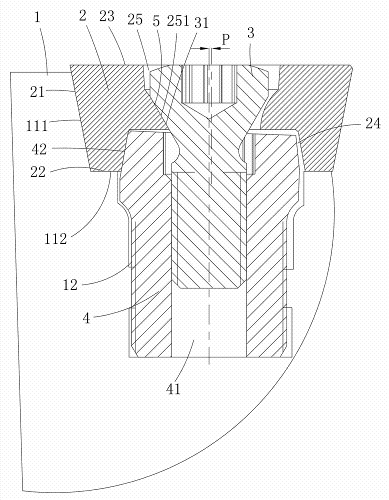
[0017] Such as figure 1 , figure 2 , image 3 As shown, an embodiment of the cutting tool of the present invention includes a cutter body 1, a blade 2 and a fastening screw 3. The blade 2 includes a blade bottom surface 22, a blade top surface 23, and is connected between the blade bottom surface 22 and the blade top surface 23 The blade side 21. The knife body 1 is provided with at least one set of slot 11 for mounting the blade 2. The slot 11 includes a slot side surface 111 and a slot bottom surface 112. The slot bottom surface 112 is provided with a positioning screw hole 12, the slot side surface 111 and the knife The included angle between the groove bottom surfaces 112 is an obtuse angle. A pin 4 with an internal threaded hole 41 is screwed into the positioning screw hole 12. The blade 2 is sleeved on the head of the pin 4 through a groove ...


PUM


Abstract

The invention discloses a cutting tool, which comprises a body, a blade and a fastening screw, wherein the body is provided with at least one group of tool slots; each tool slot comprises a tool slot side face and a tool slot bottom surface; the tool slot bottom surface is provided with a positioning screw hole; an included angle between the tool slot side face and the tool slot bottom surface is an obtuse angle; a pin with an internal threaded hole is screwed in the positioning screw hole; the blade is sleeved on the head of the pin through a groove formed in a blade bottom surface and is connected with the pin through the fastening screw; when the fastening screw is not screwed up, the blade side face is contacted and matched with the tool slot side face; a pre-tightening gap S is remained between the blade bottom surface and the tool slot bottom surface; and when the fastening screw is screwed up, the blade slides to the blade bottom surface to be contacted and matched with the tool slot bottom surface along the tool slot side face, and the inner side wall of the groove is abutted against the head of the pin to produce elastic deformation so as to clamp the blade between the tool slot side face and the head of the pin. The cutting tool has the advantages of simple and compact structure, convenience in machining and manufacturing, low production cost, convenience in disassembly and the like.

Description

Technical field [0001] The present invention mainly relates to the field of cutting tools, in particular to a cutting tool with anti-flying structure. Background technique [0002] In the cutting process of aluminum alloy rotary cutting tools, a high spindle speed (10000 <n <35000r / min) and high cutting speed (1500 <Vc <6000m / min) in order to greatly improve processing efficiency and improve surface quality. In the process of high-speed cutting, the huge centrifugal force generated by high-speed rotation will make the cutting blades more likely to fly out and cause machining accidents. Therefore, a reasonable anti-fly structure is particularly important for cutting tools. [0003] In the aluminum alloy cutting industry, most cutting tool companies now use the serrated structure of the sipe positioning bottom surface to prevent the blade from flying out. For example, Sandvik's patent publication number CN1611316A discloses a cutting tool that can be indexed. The positio...

Claims


Application Information

Patent Timeline
IPC IPC(8): B23B27/16B23B29/04
Inventor 吕长江杨志平向侠
Owner ZHUZHOU CEMENTED CARBIDE CUTTING TOOLS CO LTD
Why Eureka
Try Eureka