Combined chamfering blade with blade pieces

A split-type, chamfering knife technology, applied in the direction of gear tooth manufacturing equipment, gear teeth, gear tooth manufacturing tools, etc., can solve the problems of narrow application range and single function, so as to improve product quality, improve efficiency, and reduce cutting tools The effect of usage

Inactive Publication Date: 2012-10-31
上海星合机电有限公司
View PDF4 Cites 4 Cited by
  • Summary
  • Abstract
  • Description
  • Claims
  • Application Information

AI Technical Summary

Problems solved by technology

The present invention solves the problems of single function and narrow application range of existing circular blades

Method used


Image

  • Combined chamfering blade with blade pieces
  • Combined chamfering blade with blade pieces

Examples


Embodiment Construction

[0014] Further illustrate by the following examples.

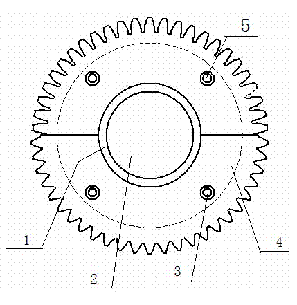
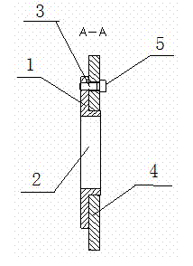
[0015] Cutter body 1 center has axle hole 2, and cutter blade 4 is coaxially installed on the cutter body 1, and cutter blade 4 is a group of 2-6 only to form a complete circular blade, and cutter blade 4 is semicircle or sector-shaped.

[0016] A screw hole 3 is provided along the periphery of the central axis hole 2 of the cutter body 1 .

[0017] There is a pillow block around the shaft hole 2 on the cutter body 1, and a screw hole 3 is opened on the pillow block.

[0018] There are cutter teeth on the outer edge of the knife flap 4, and screw holes 3 are opened on the inner edge periphery.

[0019] The present invention integrates a plurality of blades 4 with different tooth edges in the cutter body 1, and these blades 4 are combined into a complete blade to realize multifunctional chamfering on the same chamfering knife, and each blade 4 realizes its own The function of corresponding to a certain function requir...


PUM


Abstract

A combined chamfering blade with blade pieces adopts the structure that a shaft hole (2) is formed in the middle of a blade body (1); and the blade pieces (4) are coaxially mounted on the blade body (1), are 2 to 6 blades which form an integral circle in an encircling manner, and are semicircular or sectorial. As the combined chamfering blade integrating a plurality of blade pieces with different toothed edges can conduct multi-purpose processing on the end surface of a gear (even the side surface outline of the gear can be processed to be stepped) through one-time processing. Under the premise that the product quality is improved, the combined chamfering blade has the advantages that the use frequency of a cutter is reduced, the efficiency is improved, the cost is reduced, and the service life of the cutter is prolonged.

Description

technical field [0001] The invention relates to a tool for international patent classification B23B turning, boring or B24D grinding, polishing or sharpening, belonging to the technical field of gear end face chamfering, in particular to a split-type assembly chamfering tool. Background technique [0002] Commonly used chamfering knives all make the same kind of teeth on the same blade; if the number of teeth is 100 blades, then the shape of the 100 teeth evenly distributed on the circumference is exactly the same. The existing chamfering knife is simple in design and manufacture, has a single function, and it is difficult to expand the chamfering function. For example, when the gear side is processed with steps, the existing chamfering tool can only process a part of the step, and cannot perform chamfering on the entire end surface profile; Only one chamfer can be processed, but two or more chamfers cannot be processed. [0003] In the known technologies, especially ...

Claims


Application Information

Patent Timeline
Patent Type & Authority Applications(China)
IPC IPC(8): B23F21/00B23F19/10
Inventor 蒋能唐钧
Owner 上海星合机电有限公司
Why Eureka
Try Eureka