
Fluid detection jig

A technology of fluid detection and fixtures, which is applied in printing and other directions, can solve problems such as time-consuming, and achieve the effects of reducing costs, saving assembly manpower and working hours

Inactive Publication Date: 2012-10-31
KINPO ELECTRONICS
View PDF5 Cites 0 Cited by
  • Summary
  • Abstract
  • Description
  • Claims
  • Application Information

AI Technical Summary

Problems solved by technology

However, if the test results of the cleaning device do not meet the requirements, the assembly personnel need to spend time and effort to disassemble the cleaning device from the business machine for replacement or repair.

Method used


Image

  • Fluid detection jig
  • Fluid detection jig
  • Fluid detection jig

Examples


Embodiment Construction

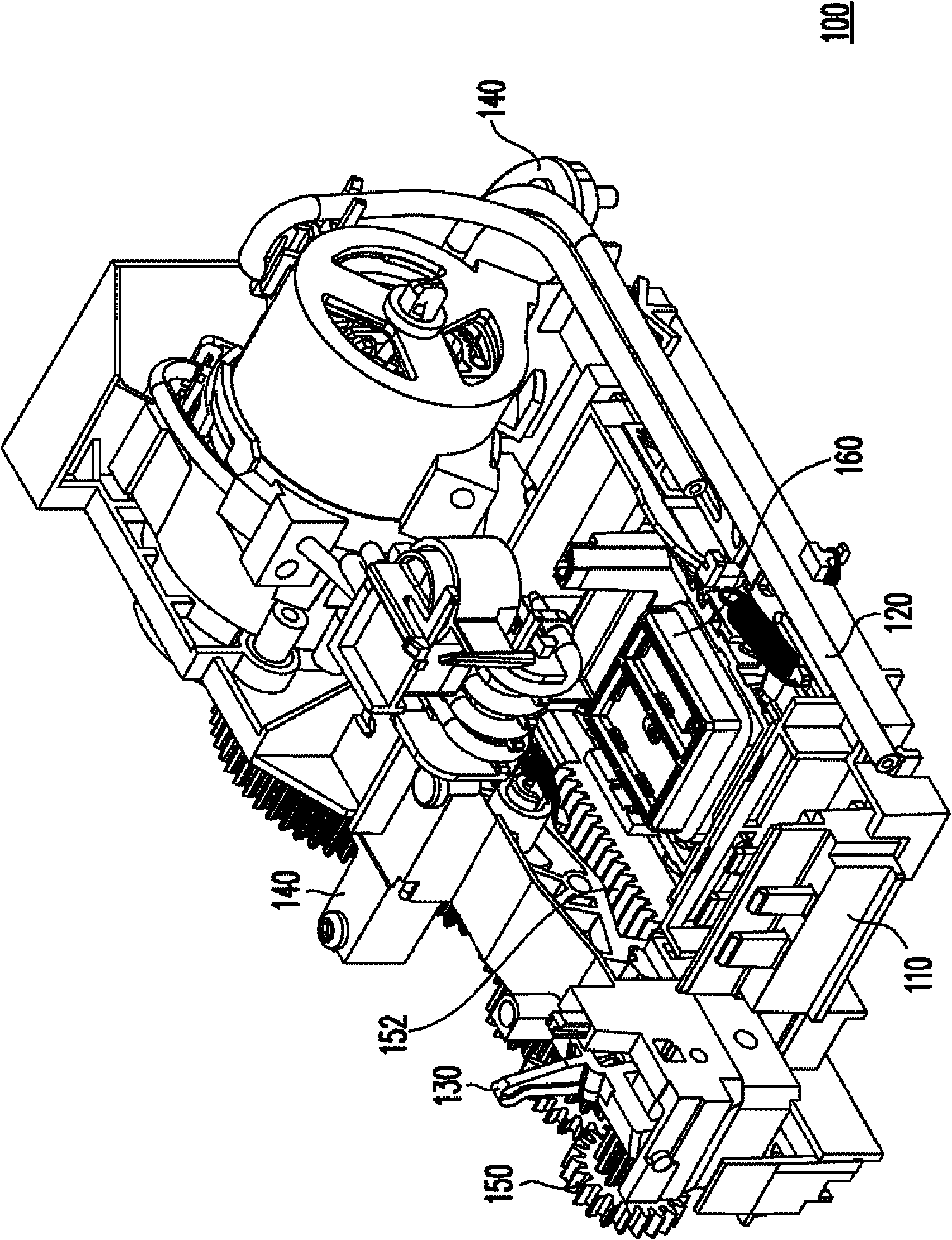
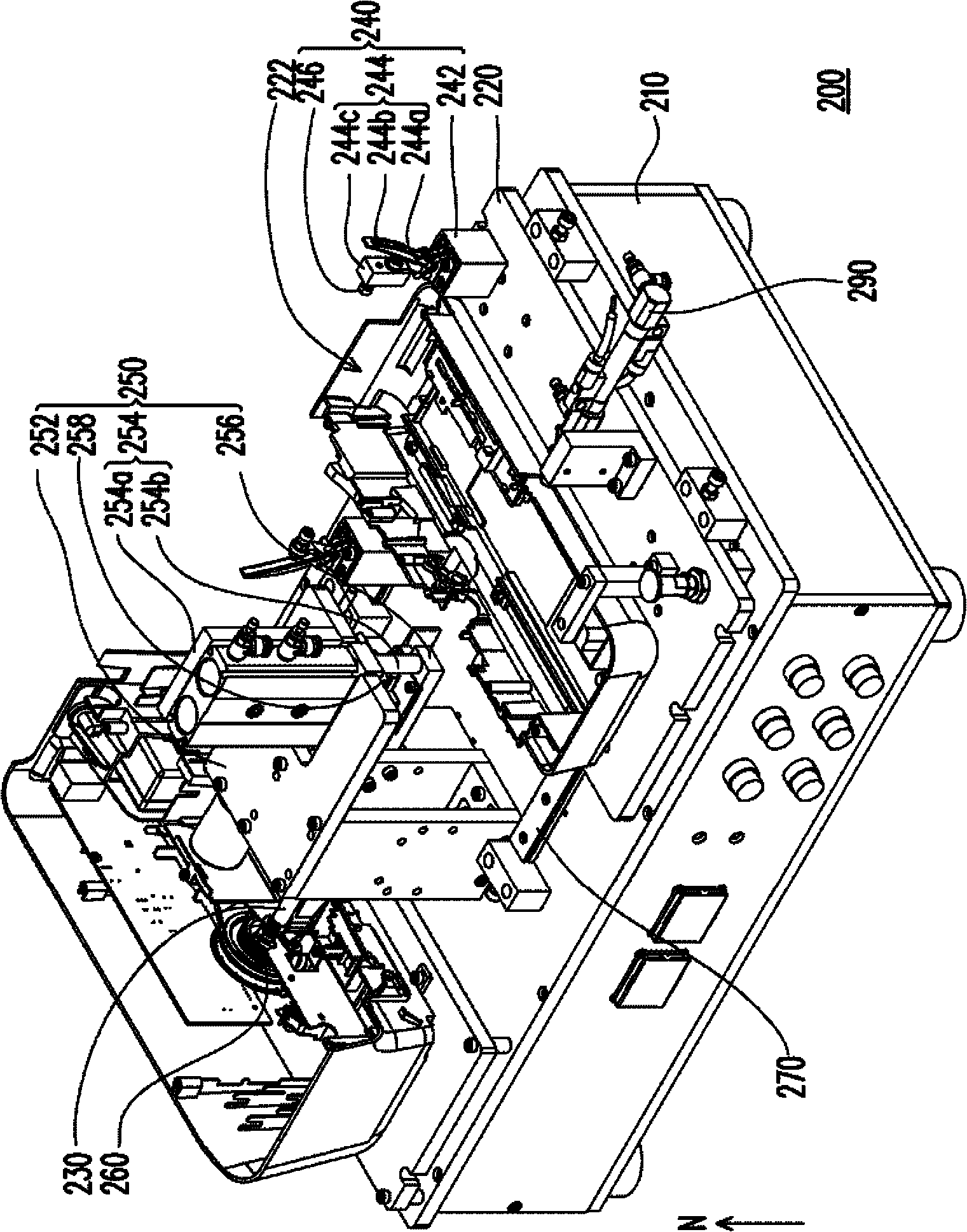
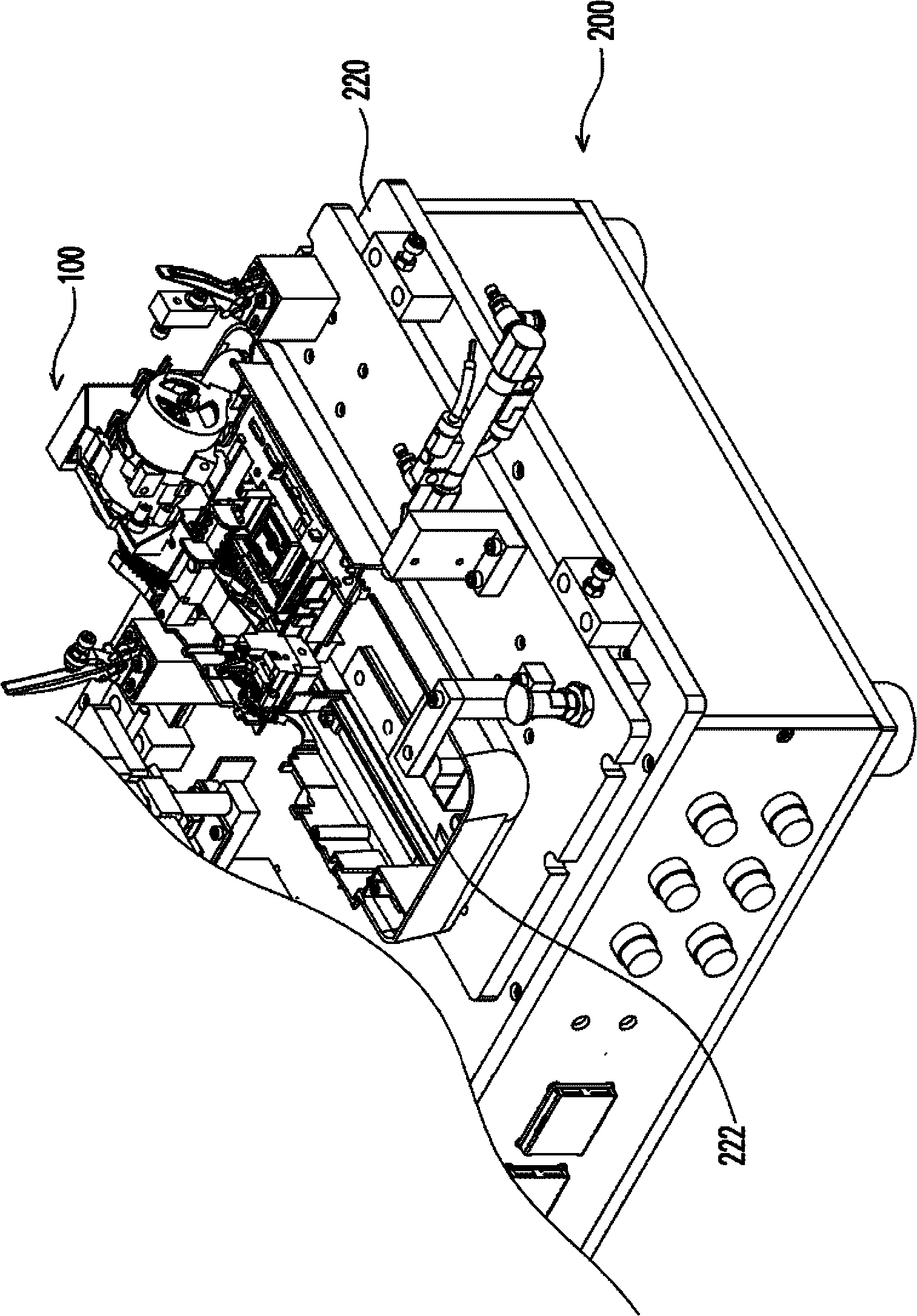
[0067] The fluid detection jig of the present invention is used to test whether the cleaning device can operate and meet the set requirements before the cleaning device is installed in the inkjet printer (or business machine). Before installing the cleaning device on the inkjet printer (or office machine), first use the fluid detection fixture of the present invention to detect the cleaning device, and then install the cleaning device on the inkjet printer (or office machine) after the cleaning device passes the test. or transaction machine). Compared with the known cleaning device that needs to be installed in an inkjet printer (or office machine) before the cleaning device can be tested, the fluid detection jig of the present invention is used to first test the cleaning device, and after the cleaning device passes the test Then it is loaded into the inkjet printer (or business machine), so it can save the assembly manpower and man-hours of disassembly, replacement or repair if...


PUM


Abstract

A fluid detection jig is suitable for detecting a cleaning device and comprises a base, a testing platform, a transmission shaft, a positioning fixture and a detection device, wherein the testing platform, the transmission shaft, the positioning fixture and the detection device are arranged on the base, and the testing platform is suitable for moving between an assembling position and a testing position relative to the base. The transmission shaft is provided with a first tail end, a second tail end and a gear, wherein the gear is arranged at the first tail end relatively close to the testing platform. The positioning fixture corresponds to a positioning structure of the cleaning device. The detection device comprises a positioning body, a pneumatic cylinder and a detection unit, wherein the positioning body is arranged on the base and positioned on a moving path of the testing platform, the pneumatic cylinder is arranged on the positioning body, and the detection unit is arranged on one side of the pneumatic cylinder relatively close to the base.

Description

technical field [0001] The invention relates to a testing jig, and in particular to a fluid testing jig for testing a cleaning device. Background technique [0002] With the increasing use of computers and the Internet, the demand for printing documents with printers or office machines is increasing. Based on price considerations, compared to more expensive laser printers, inkjet business machines are still a more common choice for families. The inkjet business machine mainly utilizes an inkjet head arranged in it to accurately eject ink to a designated position on a paper (or other carrier), so as to display characters or images on the paper. However, during the inkjet printing process, residual ink droplets are likely to accumulate around the nozzles of the inkjet head, or powder particles or paper dust from the paper surface may accumulate. Therefore, the nozzles of the inkjet head are easily clogged, resulting in deterioration of printing quality. In detail, the so-ca...

Claims


Application Information

Patent Timeline
Patent Type & Authority Applications(China)
IPC IPC(8): B41J2/165
Inventor 林尧宗
Owner KINPO ELECTRONICS
Learn More