Decorative ribbon cutting machine

A cutting machine and decorative tape technology, applied in the cutting of textile materials, textiles and papermaking, etc., can solve the problems of low work efficiency and burrs

Inactive Publication Date: 2012-10-31
WUJIANG YUANXING SHOES
View PDF5 Cites 1 Cited by
  • Summary
  • Abstract
  • Description
  • Claims
  • Application Information

AI Technical Summary

Problems solved by technology

[0002] In the slipper processing technology in the prior art, the trimming of the decorative band used to decorate the slipper is usually cut by the worker with scissors, the work efficiency is low, and the trimmed edge will produce burrs

Method used


Image

  • Decorative ribbon cutting machine
  • Decorative ribbon cutting machine
  • Decorative ribbon cutting machine

Examples


Embodiment Construction

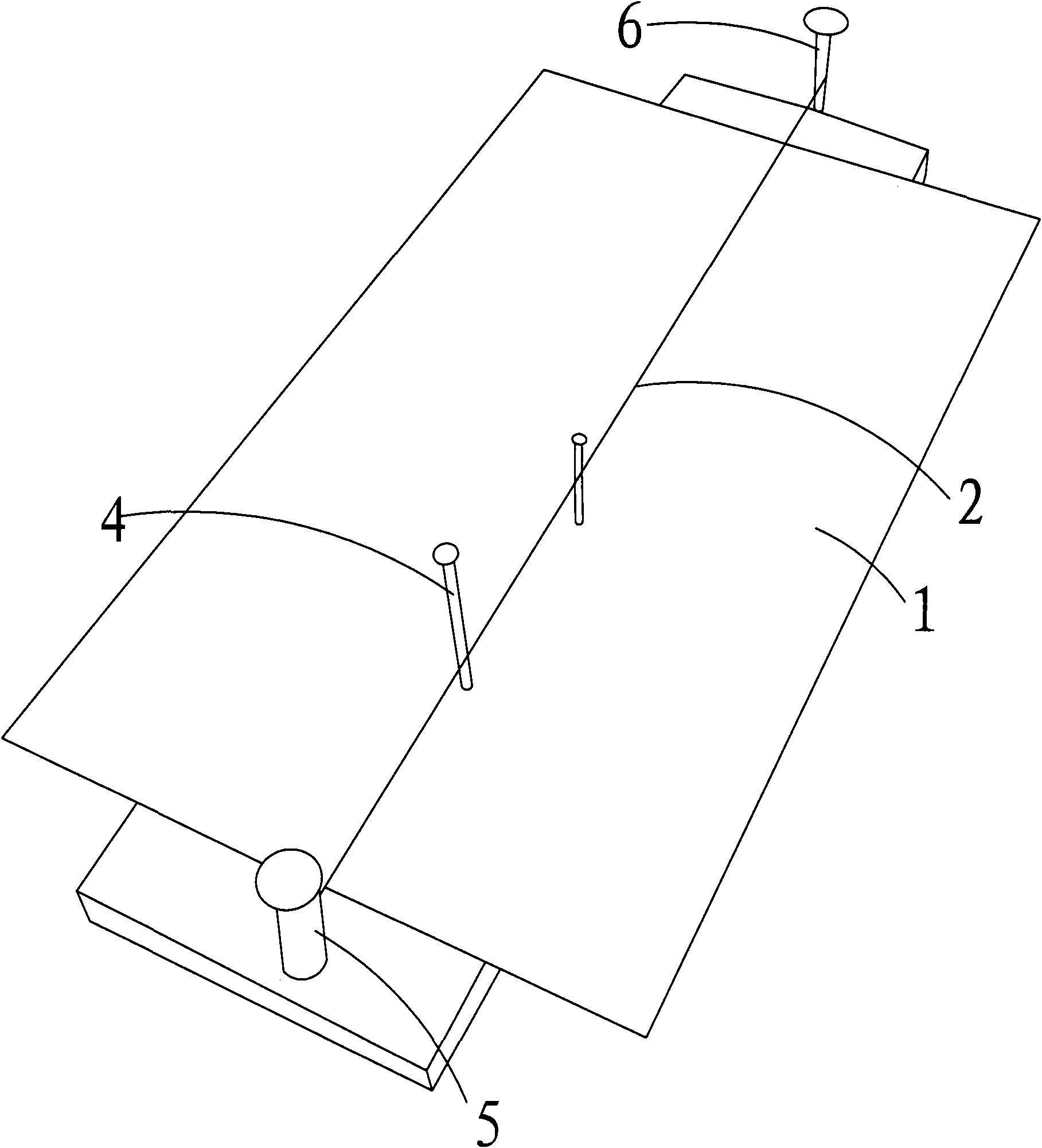
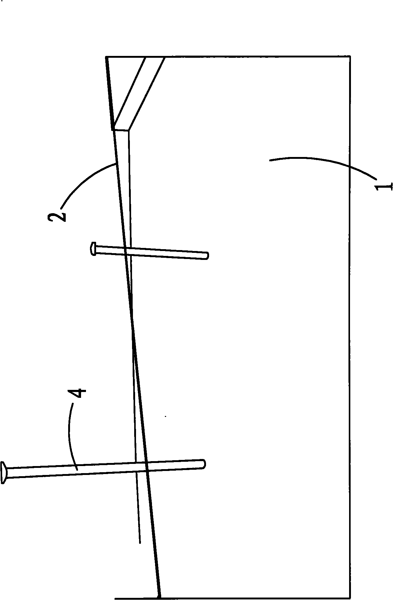
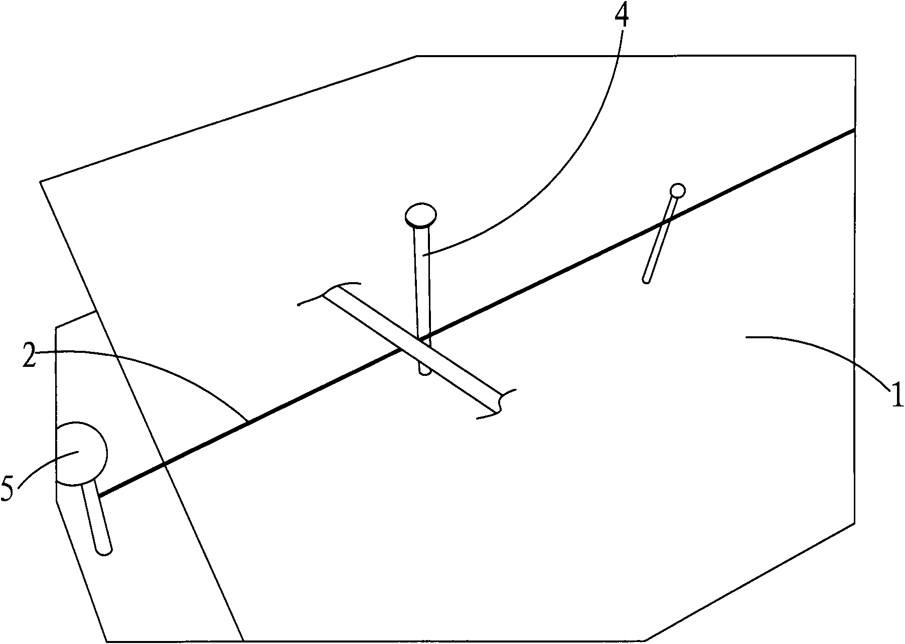
[0014] as attached figure 1 - attached Figure 4 As shown, a decorative tape cutting machine includes a frame 1 , a heating wire 2 arranged on the frame 1 , and a power supply 3 electrically connected to the heating wire 2 . After the power supply 3 is connected, the heating wire 2 generates heat, and the decorative tape can be cut off only by being close to the heating wire 2 .

[0015] as attached figure 1 - attached image 3 As shown, the frame 1 is also provided with positioning columns 4 . It is convenient to cut the decorative belt into a certain size, and the operation is convenient.

[0016] as attached figure 1 , attached image 3 As shown, the frame 1 is fixed with a first mounting column 5 and a second mounting column 6, and the heating wire 2 is connected between the first mounting column 5 and the second mounting column 6 Between, the positioning column 4 is located between the first installation column 5 and the second installation column 6 .

[0017] As ...


PUM


Abstract

The invention relates to a decorative ribbon cutting machine. The decorative ribbon cutting machine comprises a stand, an electric heating wire and a power supply, wherein the electric heating wire is arranged on the stand, and the power supply is electrically connected with the electric heating wire. In the invention, an operator places a decorative ribbon on the decorative ribbon cutting machine for cutting, and the decorative ribbon is cut through the heating of the electric heating wire; high work efficiency is achieved; and a cut edge part generates no burr.

Description

technical field [0001] The invention relates to a decorative tape cutting machine. Background technique [0002] In the slipper processing technology in the prior art, the trimming of the decorative band used to decorate the slipper is usually cut by the worker with scissors, the work efficiency is low, and the trimmed edge will produce burrs. Contents of the invention [0003] The technical problem to be solved by the present invention is to provide a decorative tape cutting machine. [0004] In order to solve the above technical problems, a technical solution adopted by the present invention is: a decorative tape cutting machine, including a frame, a heating wire arranged on the frame, and a power supply electrically connected to the heating wire . [0005] In some embodiments, the frame is further provided with a positioning column. [0006] In some further embodiments, the frame is fixed with a first mounting column and a second mounting column, and the heating wire...

Claims


Application Information

Patent Timeline
IPC IPC(8): D06H7/22
Inventor 蒋学兴
Owner WUJIANG YUANXING SHOES
Why Eureka
Try Eureka