Method for testing thermal resistance of high-power silicon carbide diode

A technology of silicon carbide diodes and testing methods, applied in the direction of thermal development of materials, etc., can solve the problems of long time, complicated operation method and high cost, and achieve the effect of wide application range, simple operation and low cost

Active Publication Date: 2012-10-31
SOUTHEAST UNIV
View PDF4 Cites 13 Cited by
  • Summary
  • Abstract
  • Description
  • Claims
  • Application Information

AI Technical Summary

Problems solved by technology

However, the structure of the infrared scanning equipment is complicated, the operation method is complicated, and the test efficiency is low. The assessment of finished devices or chips cannot meet the requirements
Especially for the thermal resistance measurement of high-power diodes, the technology in this area is lacking.

Method used


Image

  • Method for testing thermal resistance of high-power silicon carbide diode
  • Method for testing thermal resistance of high-power silicon carbide diode
  • Method for testing thermal resistance of high-power silicon carbide diode

Examples


Embodiment Construction

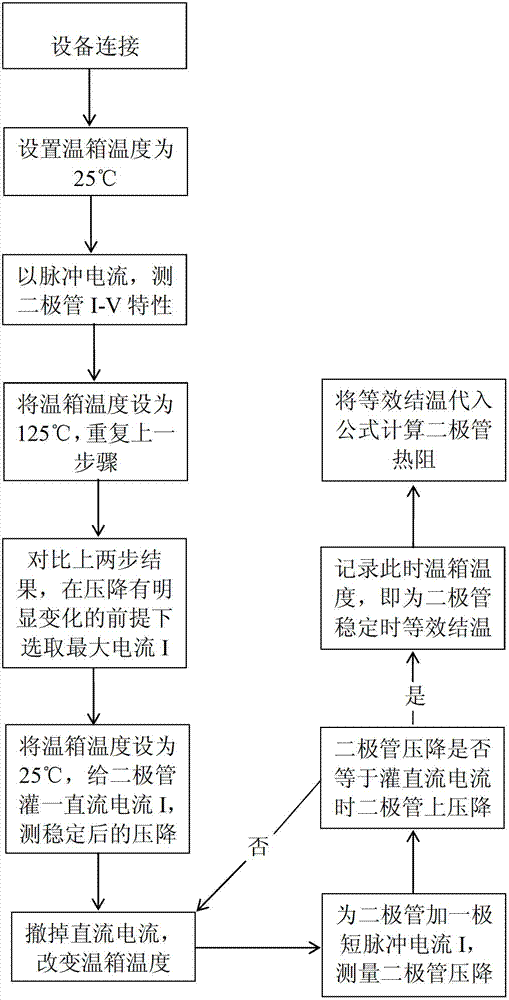
[0027] A high-power silicon carbide diode thermal resistance test method:

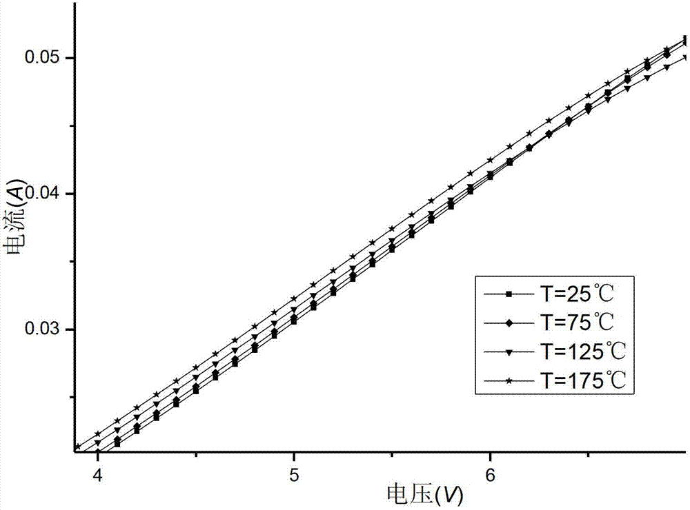
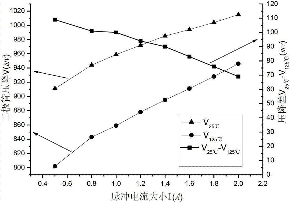
[0028] Step 1. Place the insulating substrate on which the diode to be tested is placed in the temperature control box, and adjust the temperature control box to 25°C. According to the scope of the safe working area of ​​the diode to be tested and ensure that the device to be tested can work normally, Apply a single current pulse with a pulse width of 200μs to both ends of the diode to be tested, and the pulse current values ​​are 0.5A, 0.8A, 1.0A, 1.2A, 1.4A, 1.6A, 1.8A, and 2.0A in sequence, and record them respectively The voltage drop across the diode under different pulse currents,

[0029] Step 2. Raise the temperature of the incubator to 125°C. According to the range of the safe working area of ​​the diode to be tested and ensure that the device to be tested can work normally, apply a single current pulse with a pulse width of 200 μs to both ends of the diode to be tested. The current values ​​...


PUM


Abstract

The invention relates to a method for testing thermal resistance of a high-power silicon carbide diode, which comprises the following steps: putting an insulation substrate with a device to be tested in a temperature-controlled cabinet, regulating the temperature of the temperature-controlled cabinet to 25 DEG C, applying a transient monopulse current to the diode, and testing the diode voltage drop corresponding to different pulse current magnitudes; heating the temperature-controlled cabinet to 125 DEG C, measuring the diode voltage drop corresponding to different pulse current magnitudes, comparing with the values measured at 25 DEG C, and taking a maximum current on the premise of ensuring obvious change of voltage drop; dropping the temperature of the temperature-controlled cabinet to 25 DEG C, applying a direct current with the magnitude selected above to the diode, and measuring the diode voltage drop after the junction temperature becomes stable; changing the temperature of the temperature-controlled cabinet, and testing the diode voltage drop at this time by using pulse current until the diode voltage drop at a certain temperature is equal to the diode voltage drop when applying the direct current, thus, the temperature of the temperature-controlled cabinet at this time is the equivalent junction temperature; and computing the thermal resistance of the diode according to the equivalent junction temperature by using a thermal resistance computing formula.

Description

technical field [0001] This technology belongs to the field of semiconductor device measurement technology in microelectronics technology, and especially relates to the junction temperature and thermal resistance measurement method of high-power silicon carbide diodes. High power refers to diodes whose normal working power can be above 2W. Background technique [0002] Silicon carbide is a new type of composite material, which has been widely used due to its large band gap, high temperature resistance, low mobility, high electrical conductivity, and good thermal conductivity, which further promotes the development of high-voltage and high-power diodes. development of. Although the silicon carbide material has good thermal conductivity, it needs to be packaged for the convenience of the use of the diode. The chip provides electrical connections and mechanical bearings to make it easy to operate and use, and provides a standard for users of large-scale integrated circuits. Th...

Claims


Application Information

Patent Timeline
Patent Type & Authority Applications(China)
IPC IPC(8): G01N25/20
Inventor 刘斯扬张春伟卫能钱钦松孙伟锋陆生礼时龙兴
Owner SOUTHEAST UNIV
Why Eureka
Try Eureka