Current transformer

A technology for current transformers and iron cores, applied in the directions of inductors, transformer/inductor cores, transformer/inductor coils/windings/connections, etc. The output waveform is easy to saturate and distort, and achieve the effect of eliminating the secondary and trailing after fault removal, the number of secondary turns, and the large cross-section

Inactive Publication Date: 2012-10-31
NANJING JIANGBEI AUTOMATION TECH
View PDF6 Cites 4 Cited by
  • Summary
  • Abstract
  • Description
  • Claims
  • Application Information

AI Technical Summary

Benefits of technology

In this patented technology, it suggests that by increasing the size or numbers of windings on the main body of the ferrite material used for making the transformers while reducing their overall dimensions, they may have better performance characteristics such as increased efficiency and improved energy utilization compared to traditional designs without them.

Problems solved by technology

The technical problem addressed by this patented solution relating to improving the accuracy and reliability of measuring small currents in electrical systems without causing damage during their occurrence. Current methods are limited because they require high precision electronic devices for accurate measurement while maintaining stable operation over long periods of use.

Method used


Image

  • Current transformer
  • Current transformer
  • Current transformer

Examples


Embodiment 1

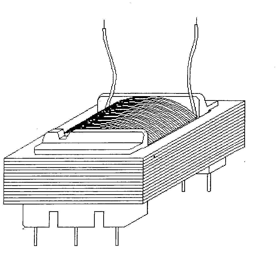
[0027] Such as figure 1 As shown, a current transformer includes an iron core, a primary winding and a secondary winding, and the cross section of the iron core is 1cm 2 -4cm 2 ; The iron core is provided with at least one air gap along the direction of cutting magnetic force lines; the number of turns of the primary winding is 1 turn-25 turns, and the number of turns of the secondary winding is 2000 turns-10000 turns; The coil diameter of the winding is Φ0.06mm-Φ0.21mm. The number of turns of the primary winding is preferably 1-15 turns, and 8 turns are used in this embodiment, and the number of turns of the secondary winding is preferably 2500 turns-6000 turns, and 2500 turns are used in this embodiment. The cross-section of the iron core refers to the cross-section of the part of the iron core that passes through the winding on one side and the secondary winding, and the cross-sectional area is 3.5cm 2 . The coil diameter of the secondary winding is 0.10mm.

[0028] Th...

Embodiment 2

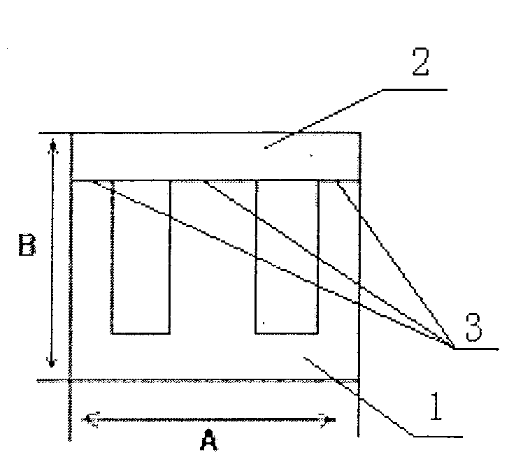
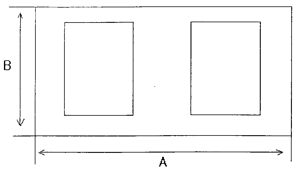
[0030] Such as Figure 7 with Figure 8 As shown, this embodiment is basically the same as Embodiment 1, the difference is that the iron core of this embodiment adopts an annular notch iron core, and the iron core cross-sectional area is 2cm 2 , the number of turns of the primary winding is 5 turns, the number of turns of the secondary winding is 4000 turns, and the coil diameter of the secondary winding is 0.08mm. The iron core may be composed of a pair of annular notched iron cores, or may be composed of at least two pairs of annular notched iron cores superimposed. Such as image 3 The illustrated embodiment employs only an annular iron core provided with an air gap 8 . The outer diameter A of the annular iron core is 18mm-40mm, the inner diameter B is 12mm-30mm, and the thickness C is 6mm-18mm. In this embodiment, the outer diameter B is preferably 36mm, the inner diameter A is 20mm, and the thickness C is 16mm. Of course, the annular iron core with air gap and the ann...


PUM

PropertyMeasurementUnit
Lengthaaaaaaaaaa
Heightaaaaaaaaaa
Widthaaaaaaaaaa

Abstract

The invention discloses a current transformer, which comprises an iron core, a primary winding and a second winding, wherein the cross section of the iron core is 1-4cm<2>; the iron core is provided with at least one air gap along a direction of cutting magnetic lines; the number of turns of the primary winding is 1-25 turns, and the number of turns of the secondary winding is 2000-10000 turns; and the diameter of a coil of the secondary winding is 0.06-0.21mm. When meeting a maximum direct-current component under 20-60 times of rated current, the current transformer can output saturated and distorted waveforms and can really reflect the attenuation state of the maximum direct-current component and eliminate the trailing phenomenon of secondary stage of waveforms according to optimized selection of parameters after faults are removed.

Description


Claims


Application Information

Patent Timeline
Owner NANJING JIANGBEI AUTOMATION TECH
Why Eureka
Try Eureka