Drive device for pivoting adjustable blades of a turbomachine

A technology of driving device and turbine, which is applied to components of pumping devices for elastic fluids, machines/engines, mechanical equipment, etc., can solve the problem of endangering the reliability and integrity of driving devices, the inability to implement micro adjustments, large load and other issues, to save weight, improve force introduction, and save space

Inactive Publication Date: 2012-10-31
SIEMENS AG
View PDF9 Cites 6 Cited by
  • Summary
  • Abstract
  • Description
  • Claims
  • Application Information

AI Technical Summary

Problems solved by technology

Rapid changes caused by small adjustment distances lead to enormous loads in the adjustment loop, which can jeopardize the reliability and integrity of the drive
On the other hand, the lever system has tolerance-induced play in the lever hinge, so that minute adjustments cannot therefore be carried out

Method used


Image

  • Drive device for pivoting adjustable blades of a turbomachine
  • Drive device for pivoting adjustable blades of a turbomachine
  • Drive device for pivoting adjustable blades of a turbomachine

Examples


Embodiment Construction

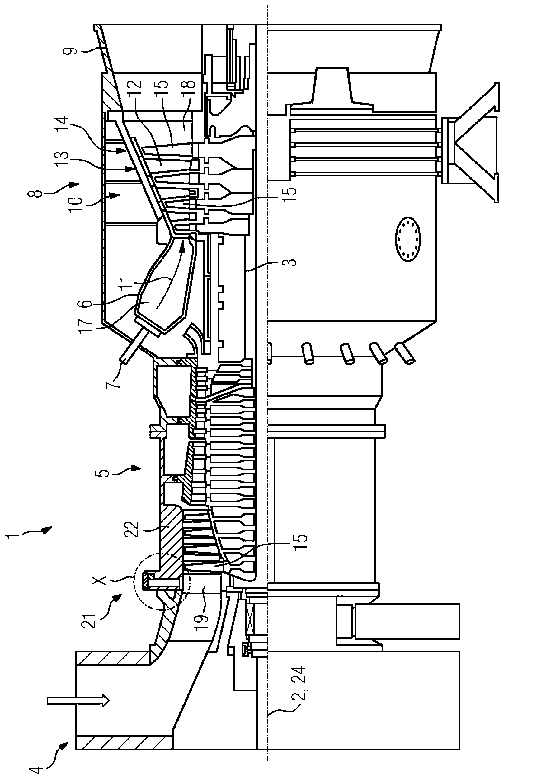
[0031] figure 1 A longitudinal partial section through a turbine designed as a stationary gas turbine 1 is shown in a longitudinal partial section. The gas turbine 1 is provided for generating electricity. The gas turbine internally has a rotor 3 mounted in rotation about an axis of rotation 2 , which is also referred to as a turbine rotor. Along the rotor 3 there follows an intake housing 4 , a compressor 5 , an annular annular combustion chamber 6 with a plurality of burners 7 arranged rotationally symmetrically to one another, a turbine unit 8 and an exhaust gas housing 9 . The annular combustion chamber 6 forms a combustion chamber 17 connected to an annular hot gas channel 18 . There, four successively connected turbine stages 10 form a turbine unit 8 . Each turbine stage 10 is formed by two blade rings. Viewed in the flow direction of the hot gas 11 generated in the annular combustion chamber 6 , each blade row 13 is followed by a row 14 formed by rotor blades 15 in ...


PUM


Abstract

The invention relates to a drive device (21) for pivoting adjustable blades (19) of a turbomachine, comprising an annular flow channel section (23) surrounded by a blade carrier (22), said section extending along the center line (24) of the blade carrier (22) and blades (19) being provided in said section in a ray-like manner, forming a ring, wherein each of the blades (19) can be pivoted about the longitudinal axis (31) thereof and each has a pin (26) which extends at least into the blade carrier (22) and is coupled to at least one adjustment ring (28) which encloses the blade carrier (22) and can be driven by means of at least one motor. In order to provide a particularly low-wear and reliable drive, the drive shaft of the motor or motors is coupled to the adjustment ring (28) or adjustment rings (28) by means of a pinion gear.

Description

technical field [0001] The invention relates to an adjustable blade drive for a pivoting turbomachine, having an annular flow channel section surrounded by a blade carrier and extending along the central axis of the blade carrier , and a circle of blades is radially provided in the flow channel section, wherein the blades are respectively pivotable around their longitudinal axes and each have a peg extending at least into the blade carrier, said pegs being coupled to the Adjustment ring turned in direction. Background technique [0002] A device of this type is eg from US 5,549,448. For adjusting the radially extending blades of the blade ring of the compressor, an adjusting ring that is concentric to the central axis of the compressor surrounds the inner housing of the compressor. Each blade of the blade ring, which is rotatable about the longitudinal axis of the blade, has a peg extending through the blade carrier and which is connected outside the housing to the adjusti...

Claims


Application Information

Patent Timeline
Patent Type & Authority Applications(China)
IPC IPC(8): F01D17/16F04D29/56
CPCF04D29/563F01D17/162
Inventor 马库斯·霍夫曼
Owner SIEMENS AG
Why Eureka
Try Eureka