Vacuum valve drive

A technology for actuators and vacuum valves, applied in the direction of sliding valves, valve details, valve devices, etc., can solve the problem of increased particle generation

Active Publication Date: 2007-11-07
VAT HLDG AG
View PDF6 Cites 5 Cited by
  • Summary
  • Abstract
  • Description
  • Claims
  • Application Information

AI Technical Summary

Problems solved by technology

Increased particle generation due to undesired material conta

Method used


Image

  • Vacuum valve drive
  • Vacuum valve drive
  • Vacuum valve drive

Examples


Embodiment Construction

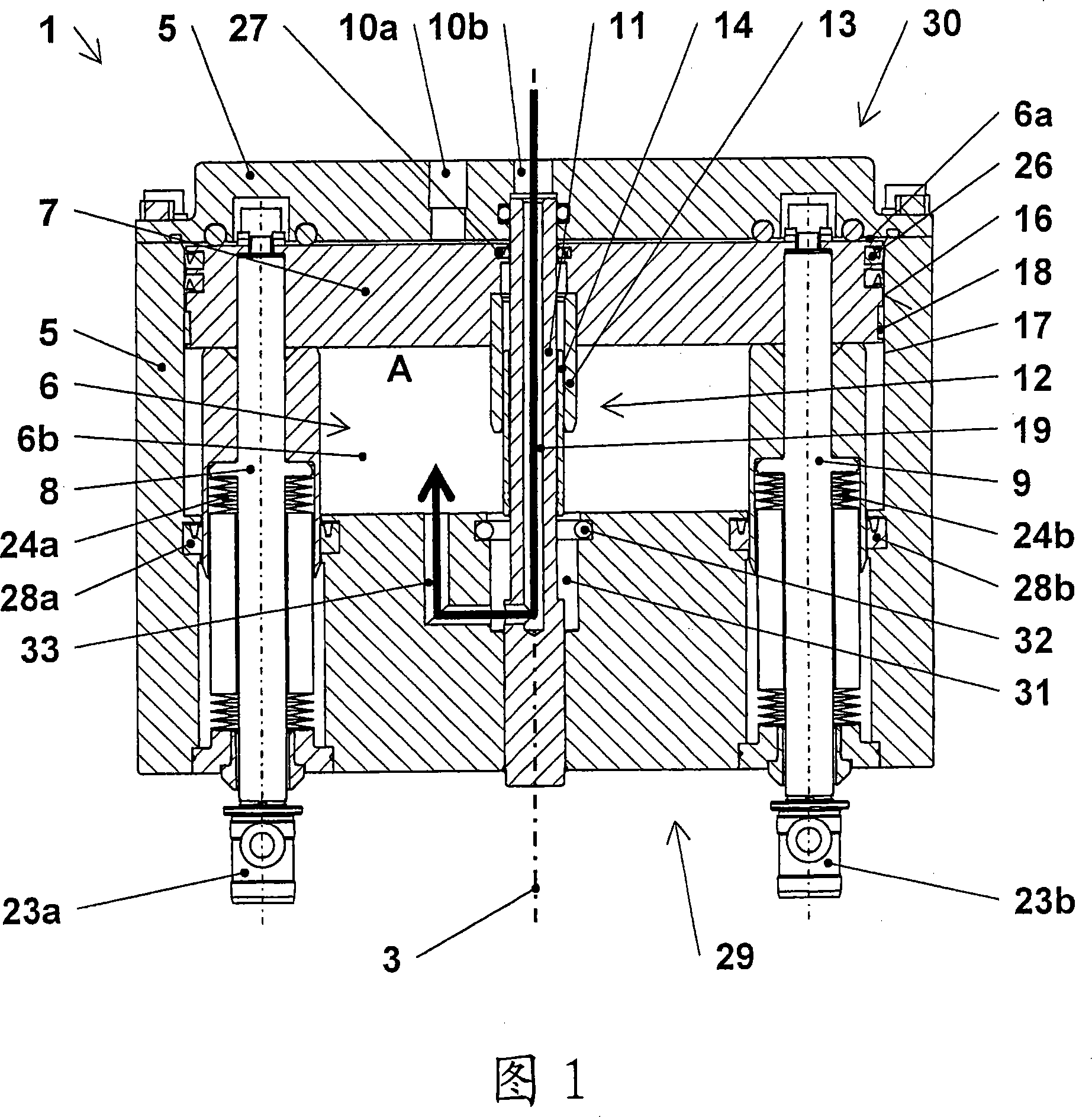
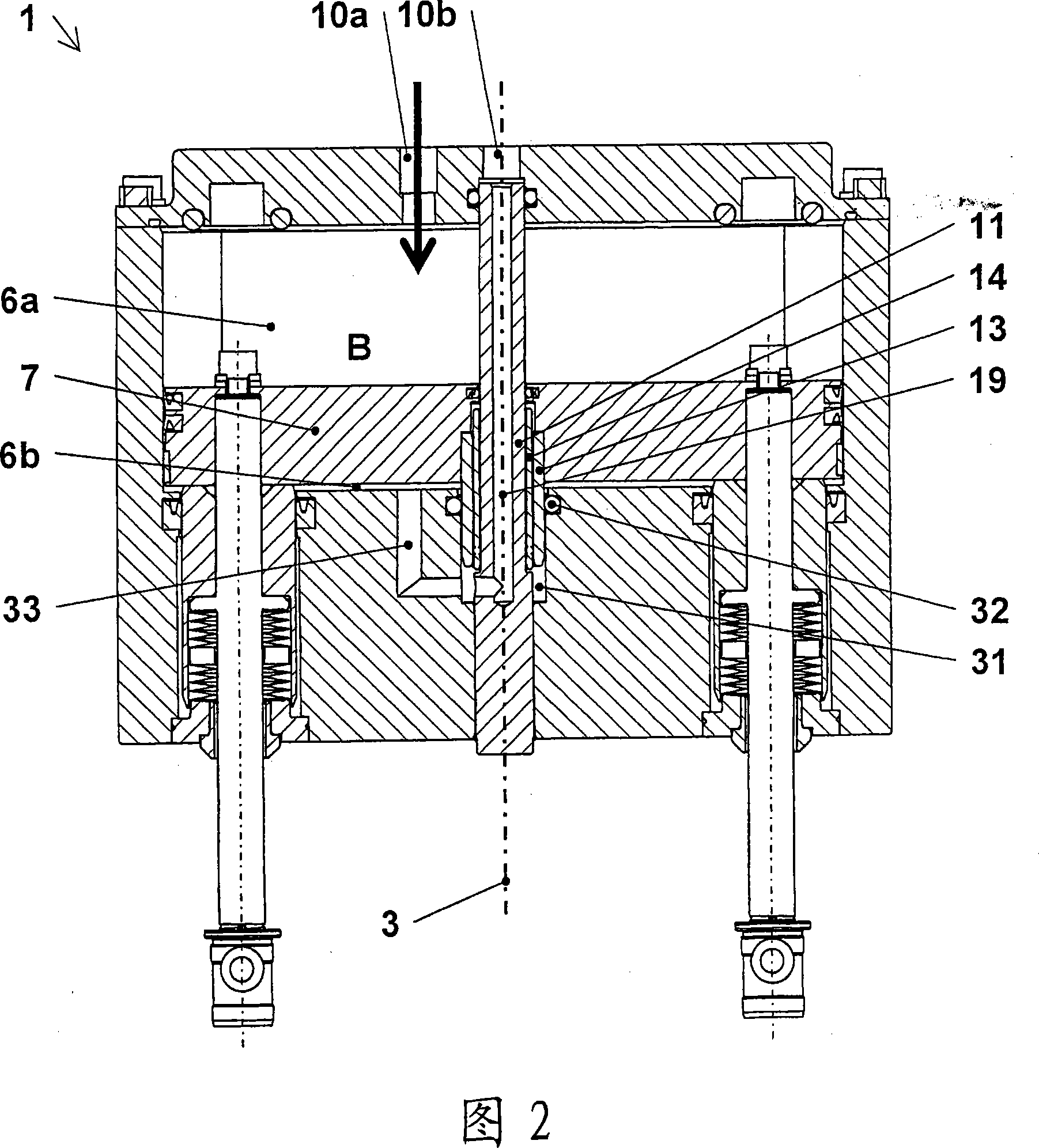
[0024] In the following, FIGS. 1 to 5 are described together in some cases, and the reference numerals that have been explained in advance in each figure will not be described separately. Figure 1 shows a possible embodiment of a vacuum valve actuator 1 according to the invention in a transverse sectional view in a fully open position A with a valve closure 2 mounted on the vacuum valve actuator 1 (cf. ) fully open. FIG. 2 shows the same vacuum valve driver 1 in the closed position B. As shown in FIG. The shown vacuum valve driver 1 comprises a multi-part driver housing 5 containing a substantially airtight working space 6 . The working space 6 has a channel-like cross-section in plan view in the direction of the adjustment axis 3 . A piston 7 displaceable along the adjustment axis 3 is arranged in the working space 6 in such a way that the piston 7 divides the working space 6 into a first pressure space 6 a on the connection side 30 and a second pressure space 6 a on the va...


PUM


Abstract

The invention relates to a vacuum valve drive ( 1 ) for linear displacement of a valve closure ( 2 ) along an adjustment axis ( 3 ) between an opened position (A) of the vacuum valve ( 4 ) and a position (B) in which it is closed gas-tight, and to a vacuum valve ( 4 ) comprising the vacuum valve drive ( 1 ). The vacuum valve drive ( 1 ) comprises a drive housing ( 5 ) which contains a gas-tight working space ( 6 ), a piston ( 7 ) inside the working space ( 6 ), which divides the working space ( 6 ) into a first and a second pressure space ( 6 a, 6 b), and at least one connecting rod ( 8; 9 ) which is led from the working space ( 6 ) in a gas-tight manner to the valve closure ( 2 ). According to the invention, a static guide rod ( 11 ) which extends centrally and parallel to the adjustment axis ( 3 ) inside the working space ( 6 ) and is led through the piston ( 7 ), and a precision linear bearing ( 12 ) between the piston ( 7 ) and the guide rod ( 11 ), are provided. By means of the guide rod ( 11 ), the piston ( 7 ) is linearly guided with high precision and centred in the working space ( 6 ) so that the valve closure ( 2 ) coupled thereto is moved with high precision and pressed onto the valve seat ( 22 ), any particle generation by metal friction being avoided. In a further development, gas pressure is applied to the second pressure space ( 6 b) via a channel ( 19 ) inside the guide rod ( 11 ).

Description

technical field [0001] The invention relates to a vacuum valve drive according to the preamble of claim 1 and a vacuum valve according to the preamble of claim 13 comprising a vacuum valve drive for using The valve closure is linearly displaceable along the adjustment axis between an open position of the vacuum valve and a hermetically closed position of the vacuum valve. Background technique [0002] Vacuum valves for substantially gas-tight closing of a flow path leading through an opening in a valve housing are known from various embodiments from the prior art. Vacuum gate valves are especially used in the field of IC and semiconductor manufacturing, which must be carried out in a protective environment free of contaminating particles as much as possible. For example, in a manufacturing plant of semiconductor wafers or liquid crystal substrates, highly sensitive semiconductor elements or liquid crystal elements pass sequentially through a plurality of processing chambers...

Claims


Application Information

Patent Timeline
IPC IPC(8): F16K31/122F16K3/02F16K51/02
CPCF16K31/1226F16K3/0254F16K51/02F16K3/314
Inventor 伯恩哈德·利乔尔托马斯·布莱哈
Owner VAT HLDG AG
Why Eureka
Try Eureka