Eureka AIR delivers breakthrough ideas for toughest innovation challenges, trusted by R&D personnel around the world.

Method and device for sending and receiving mapping cost

An overhead and quantity technology, applied in the field of optical transmission network, can solve the problem of slow adjustment process and achieve the effect of flexible adjustment

Active Publication Date: 2010-06-09
HUAWEI TECH CO LTD
View PDF3 Cites 6 Cited by
  • Summary
  • Abstract
  • Description
  • Claims
  • Application Information

AI Technical Summary

Problems solved by technology

So scaling with a step size of 1 does not provide the same scaling capability for OPUk and OPUk-Xv
[0009] In this way, in the prior art, the adjustment step of Cn is limited to 1, not only the adjustment process is slow, but also cannot provide the same adjustment capability for OPUk / OPUk-Xv; if a changed Cn value needs to be transmitted, at least 4 frames are required The adjustment can be completed, the increase / decrease indication for one frame transmission, and the changed Cn value for three frames of transmission

Method used


Image

  • Method and device for sending and receiving mapping cost
  • Method and device for sending and receiving mapping cost
  • Method and device for sending and receiving mapping cost

Examples


Embodiment 1

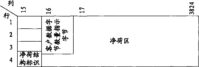
[0045] Such as Figure 5 As shown, the method of sending mapping overhead includes:

[0046] 501. Acquire a change value of the number of client data bytes received in the current transmission frame period relative to a reference value. Steps include:

[0047] 5011. Obtain the number of client data bytes received in the current transmission frame period and the last transmission frame period, and use the number of client data bytes received in the last transmission frame period as a reference value.

[0048] In the OTN frame, the client signal is placed in the payload area of ​​the frame. At the sending end, by counting the client clock in one OTN frame period, the number of bytes Cn of the client data in one OTN frame period can be obtained. Obtain the number of client data bytes received in the current transmission frame period and the last transmission frame period, and use the number of client data bytes received in the last transmission frame period as a reference value...

Embodiment 2

[0114] Such as Figure 10 As shown, the method of sending mapping overhead includes:

[0115] 1001. Acquire a change value of the number of client data bytes received in the current transmission frame period relative to a reference value. Steps include:

[0116] 10011. Acquire the number of bytes of client data in the current OTN frame period, obtain the minimum value of the number of bytes of client data received in the transmission frame period according to the client clock and the local clock, and use the minimum value as a reference value.

[0117] In an OTN frame, client signals are placed in the payload area of ​​the frame.

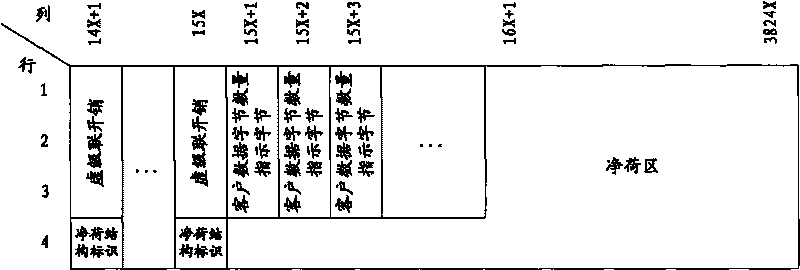
[0118] At the sending end, according to the input client signal, the client clock is recovered from the client signal through a phase-locked loop, and the client data is stored in the FIFO. The Cn value acquisition unit calculates the minimum value Cn(min) of Cn according to the client signal clock and the local system clock, and transmits Cn(min...


PUM


Abstract

The invention discloses a method and device for sending and receiving mapping cost in adaptive constant bit rate service, belonging to the optical transport network field. The invention aims to solve the problem that the prior art can not provide the same adjustment ability for OPUk and OPUk-Xv and the adjustment speed is slow. The method and device for sending and receiving mapping cost transmit the change value of the number of a plurality of customer data bytes in OTN frame and a receiving terminal performs majority decision to obtain the correct number of customer data bytes, thus increasing the reliability of data transmission. The change value is transmitted in OTN frame to provide the same adjustment ability for OPUk and OPUk-Xv; and random adjustment of the quantitative value of the customer data bytes can be realized in a certain range.

Description

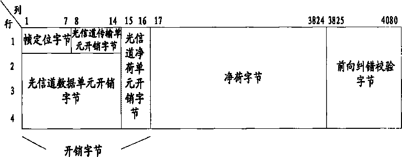
technical field [0001] The invention relates to an optical transmission network, in particular to a method and a device for sending and receiving mapping overhead in an adaptive constant bit rate service. Background technique [0002] Digital Wrapper defines an optical network frame format, such as figure 1 As shown, each frame is divided into 4 rows and 4080 columns. The 16 columns in the header are the overhead area, the 256 columns in the tail are the FEC (Forward Error Correction, Forward Error Correction) check area, and the 3808 columns in the middle are the payload area, which is used to store customer data. The 1st to 7th columns of the first row of the overhead area place frame alignment bytes, the 8th to 14th columns place optical channel transmission unit (OTUk) overhead bytes; the 2nd to 4th lines, 1st to 14th columns are optical channel data units ( ODUk) overhead bytes; columns 15 and 16 of rows 1 to 4 place optical channel payload unit (OPUk) overhead bytes....

Claims


Application Information

Patent Timeline
Patent Type & Authority Applications(China)
IPC IPC(8): H04L1/00H04L12/56H04B10/08H04Q11/00
CPCH04J3/1652
Inventor 沈瑶苏伟向俊凌骆彦行李扬丁炽武
Owner HUAWEI TECH CO LTD
Why Eureka
Eureka Blog
Learn More