
Integral type rolling machine axial adjusting device

An axial adjustment and integrated technology, which is applied in the direction of metal rolling stand, metal rolling mill stand, metal rolling, etc., can solve the problems of large matching clearance of positioning bolts to adjust the pressure plate, difficult operation, and deformation of the roll head. , to achieve the effect of firm fixed roll bearing seat, easy adjustment and operation, and enhanced fixing function

Inactive Publication Date: 2012-11-07
LAIWU IRON & STEEL GRP
View PDF8 Cites 4 Cited by
  • Summary
  • Abstract
  • Description
  • Claims
  • Application Information

AI Technical Summary

Problems solved by technology

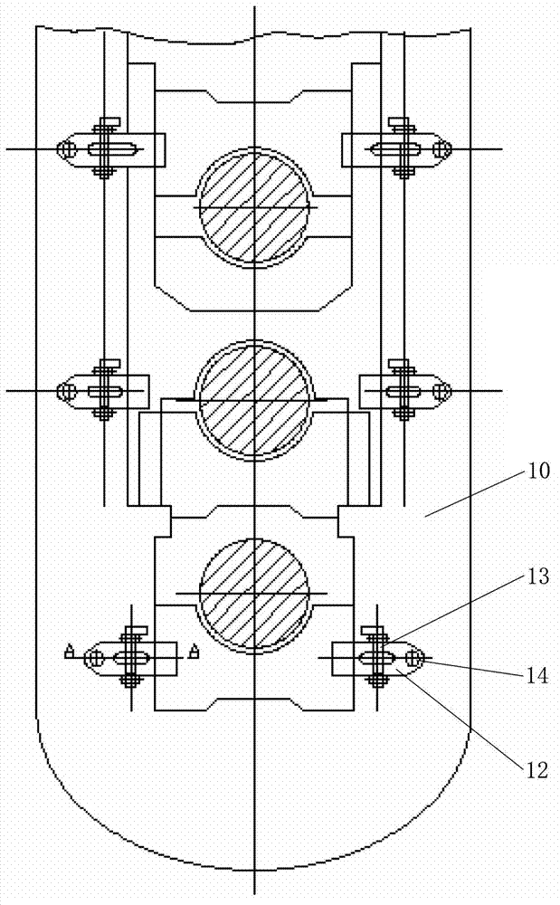
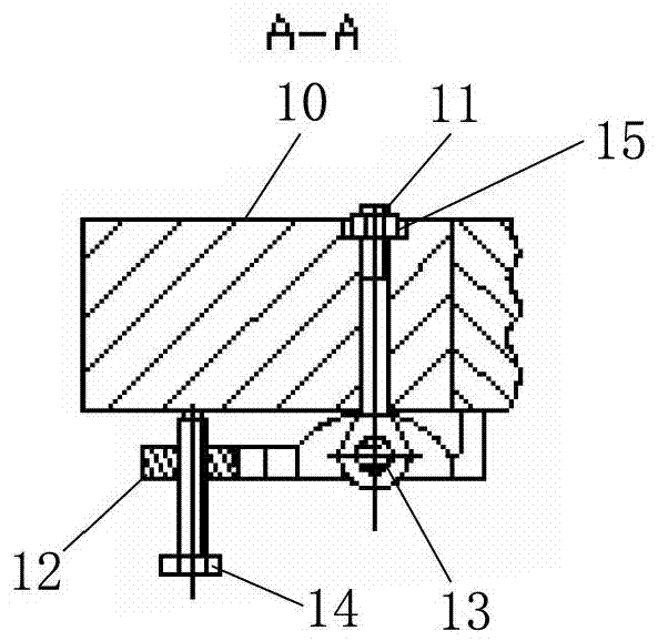
The disadvantages of this structure are: a. The positioning bolts are positioned with nuts 15 from the inside of the column of the rolling mill. Due to the influence of guide devices such as beams, the nuts cannot be tightened during the production process, and the operation is difficult; b. The nuts are easily loosened under force. The fastening screws frequently bear axial impact force, the thread fails, and the transmission system becomes unstable, causing the torx joint shaft to collide with the roll head, the material shape of the adjacent rolling mill is twisted, and collides with the inlet and outlet guides and equipment; c, the pin of the positioning bolt Holes, pin shafts, and adjusting pressure plates have a large fit gap, and the positioning bolts cannot be fixed on the column of the rolling mill; d, the structure is complex, the operation is inconvenient, and the labor intensity is high, and the rolling mill only plays the role of transmitting torque, and there is no need to adjust the shape of the material; e, process accidents If there are too many, the transmission shafts impact each other, which will aggravate the wear of the plum blossom sleeve, lead to process accidents such as bald casing, deformation of the roll head, interrupt continuous production, and increase process rolling waste.

Method used


Image

  • Integral type rolling machine axial adjusting device
  • Integral type rolling machine axial adjusting device
  • Integral type rolling machine axial adjusting device

Examples


Embodiment Construction

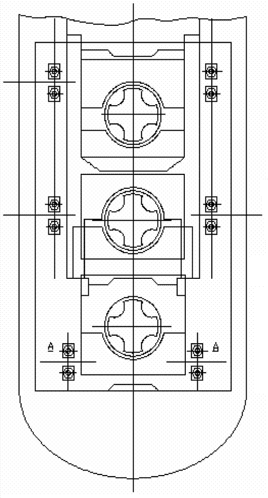
[0018] Hereinafter, embodiments of the present invention will be described in detail with reference to the drawings. Here, for convenience of description, a three-high section mill will be described as an example, and the same reference numerals will be used for the same parts in the drawings.

[0019] image 3 It shows the integral rolling mill axial adjustment device of the three-roll section steel rolling mill of the present invention. Figure 4 express image 3 The A-A line profile.

[0020] Such as image 3 and Figure 4 As shown, the integral rolling mill axial adjustment device of the present invention includes a rolling mill column 1, a roll chock 3 arranged on the rolling mill column 1 and used to support the roll 2, and a semicircular head inserted into the through hole 5 of the rolling mill column 1 Bolt 4, integral axial pressure plate 6 for fixing and adjusting roll chock 3.

[0021] Wherein, three openings are provided on the integral axial pressure plate 6...


PUM

PropertyMeasurementUnit
thicknessaaaaaaaaaa

Abstract

The invention provides an integral type rolling machine axial adjusting device, comprising a rolling machine upright (1), a roller bearing block (3), multiple cup head bolts (4) which are inserted into a through hole (5) of the rolling machine upright (1), an integral type axial pressure plate (6) used for fixing and adjusting the roller bearing block (3) and multiple flat hole slots (7) which are formed on the integral type axial pressure plate (6), wherein the integral type axial pressure plate (6) is sheathed on the multiple cup head bolts (4) which penetrate through the through hole (5) of the rolling machine upright by virtue of multiple flat hole slots (7), the multiple cup head bolts (4) are respectively added with half cylindrical pads (8), and the half cylindrical pads are respectively fastened and located by virtue of nuts (9).

Description

technical field [0001] The invention relates to the technical field of steel rolling machinery, in particular to an integral rolling mill axial adjustment device. Background technique [0002] In order to maintain the correct position of the roll pass, it is necessary to move or fix the roll axially and bear the axial force and rolling torque. Therefore, on the outer side of the column of the rolling mill, the parts corresponding to the roll bearings are respectively equipped with axial adjustment devices, which are generally arranged in pairs or singly. The purpose of installing the axial adjustment device is to adjust the axial position of the rolls, to ensure the alignment of the inlet and outlet guides and the working pass, so as to control the shape, size and flatness of the rolled piece. [0003] At present, the axial adjustment device of the section steel rolling mill is a split type, which is divided into three types: upper roll, middle roll and lower roll, and the ...

Claims


Application Information

Patent Timeline
Patent Type & Authority Applications(China)
IPC IPC(8): B21B31/18
Inventor 秦东姜艳东郭磊王允吴玉峰陈广泉
Owner LAIWU IRON & STEEL GRP
Learn More