Vertical gravitational flow conveying device for concrete

A conveying device and concrete technology, which is used in shaft equipment, earth-moving drilling, mining equipment, etc., can solve the problem of uncontrollable concrete falling state, and achieve the effect of reducing aggregate separation and continuous conveying.

Inactive Publication Date: 2012-11-07
SINOHYDRO BUREAU 5
View PDF6 Cites 10 Cited by
  • Summary
  • Abstract
  • Description
  • Claims
  • Application Information

AI Technical Summary

Problems solved by technology

In the above structure, there is no valve switch on the feeding conduit, so the falling state of the concrete in the conveying pipe cannot be controlled, and the above problems still exist

Method used


Image

  • Vertical gravitational flow conveying device for concrete

Examples


Embodiment Construction

[0014] The present invention will be further described below in conjunction with accompanying drawing:

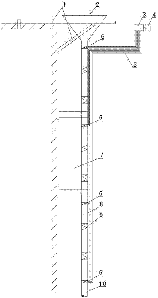
[0015] Such as figure 1 As shown, the present invention includes a hopper 2, a conveying pipe 8, a butterfly valve 6, a distribution box 3 and a control panel 4, the outlet at the lower end of the hopper 2 is connected to the upper end of the conveying pipe 8, the butterfly valve 6 is installed on the conveying pipe 8, and the butterfly valve 6 includes multiple, evenly distributed on the delivery pipe 8, the uppermost butterfly valve 6 is installed on the upper part of the delivery pipe 8 near the top position, the distance between adjacent butterfly valves 6 is 30 meters, the control input of each butterfly valve 6 The terminals are respectively connected to the control output terminals of the control panel 4 through the distribution box 3, and the connection cable 5 is also shown in the figure.

[0016] Such as figure 1 As shown, an S-shaped bend 9 is arranged in the d...


PUM


Abstract

The invention discloses a vertical gravitational flow conveying device for concrete. The vertical gravitational flow conveying device comprises a hopper, a conveying pipe, a butterfly valve, a power distribution box and a control disk, wherein a material outlet at the lower end of the hopper is connected with the upper end of the conveying pipe; the butterfly valve is arranged on the conveying pipe; and the control output end of the control disk is connected with the control input end of the butterfly valve through the power distribution box. According to the vertical gravitational flow conveying device, the switch-on state and the switch-off state of the butterfly valve are controlled through the control disk, so that an aim that the concrete in the hopper is controlled to flow from top to bottom can be fulfilled. The vertical gravitational flow conveying device has the advantages of 1, self-flowing, namely the concrete can freely fall down from top to bottom under the action of gravity without any external power; 2, conveying with a full pipe, namely in a process of conveying the concrete, the concrete is always filled in the pipe, so that a phenomenon of aggregate separation can be reduced; 3, continuity, namely the concrete is continuously supplied during conveying, so that the phenomenon of the aggregate separation can be reduced; and 4, controllability, namely the vertical gravitational flow conveying device mainly comprises an electric and manual control system of the butterfly valve, so that full and continuous conveying can be realized.

Description

technical field [0001] The invention relates to a concrete conveying device during concrete construction in a deep well, in particular to a concrete vertical gravity conveying device. Background technique [0002] In the construction of deep shafts and underground projects, the vertical transportation of concrete is often involved. If the transportation system is improper, it is easy to cause excessive impact on the concrete, separation of aggregates, and construction quality problems. The traditional vertical conveying of concrete generally adopts the direct conveying method of straight-through conveying pipes. During the conveying process, the concrete is in a state of free fall. During the initial conveying stage and when the conveying process is interrupted, the concrete on the way of falling may cause separation and fall to the bottom. When the impact force is large, part of the aggregate is separated and the construction quality is reduced. [0003] In the existing co...

Claims


Application Information

Patent Timeline
Patent Type & Authority Applications(China)
IPC IPC(8): E02D15/02E21D5/04
Inventor 吴高见贺鹏程孙林智杨建平
Owner SINOHYDRO BUREAU 5
Why Eureka
Try Eureka