
3D display device, control method and 3D display system

The technology of a display device and a control method, which is applied in the field of 3D display, can solve the problems of heavy weight, high system cost, and low display brightness, and achieve the effects of reducing comfort, energy consumption, and use cost

Active Publication Date: 2015-11-25
SHANGHAI AVIC OPTOELECTRONICS
View PDF3 Cites 0 Cited by
  • Summary
  • Abstract
  • Description
  • Claims
  • Application Information

AI Technical Summary

Problems solved by technology

[0006] In view of this, the present invention provides a 3D display device, a control method and a 3D display system to overcome the low display brightness of the 3D system in the prior art, the adopted liquid crystal response is not conducive to reducing the left and right eye crosstalk and afterimages, and the use of The high cost and weight of the shutter glasses increase the cost of the system

Method used


Image

  • 3D display device, control method and 3D display system
  • 3D display device, control method and 3D display system
  • 3D display device, control method and 3D display system

Examples


Embodiment 1

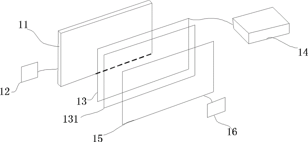
[0066] Please refer to the attached image 3 , is a structural schematic diagram of a 3D display device disclosed in an embodiment of the present invention, mainly including: a backlight source 11, a backlight source controller 12, an LCD panel 13, an LCD controller 14, a light valve (liquid crystal light valve) 15 and a light valve control device 16.

[0067] The above-mentioned backlight 11, LCD panel 13 and light valve 15 are divided into N horizontal row areas in the same manner, and the row areas on them correspond one-to-one, and the number N when dividing the horizontal row areas is greater than or equal to 1. Please refer to the attached schematic diagram for the specific division Figure 4a To attach Figure 4c .

[0068] Wherein, the width (Y direction) of each row area of ​​the LCD panel 13 may be consistent with the width of the pixels on row X, and the number of pixels on row X is greater than or equal to one.

[0069] It should be noted that the division of t...

Embodiment 2

[0102] A 3D display device is described in detail in the above disclosed embodiments of the present invention. Based on this device, the present invention also discloses a control method for a 3D display device. Please refer to the attached Figure 8 , which is a flowchart of a control method for a 3D display device disclosed in an embodiment of the present invention, mainly includes the following steps:

[0103] In step S101 , the backlight source, the LCD panel and the light valve are divided into horizontal row regions in the same manner, and the row regions divided by the three correspond one-to-one.

[0104] Step S102, receiving the 3D image data signal output by the graphics card, performing scaling and frequency conversion, and outputting left and right eye images with the same frequency.

[0105] The received 3D image data signal is processed by executing step S102. Since the 3D data image is divided into a left-eye image and a right-eye image, the actual processing is...


PUM


Abstract

The invention discloses 3D (three dimensional) display equipment, a control method and a 3D display system. The control method comprises the following steps: adopting the same method to carry out row area division on a backlight source, a LCD (liquid crystal display) panel and a light valve; receiving a 3D image data signal output by a display card, and outputting left viewpoint and right viewpoint images with consistent frequency after scaling and converting the frequency of the output 3D image data signal; scanning alternatively the left viewpoint image and the right viewpoint image of which the output sequence is determined on the basis of the row area sequentially by the LCD panel and the light valve; and controlling the light valve corresponding to the current scanning row area to perform skipping of opening or closing status. According to the equipment, the system and the control method, the purpose of improving the image display brightness can be achieved; and furthermore, polaroid glasses which are low in cost, environmental friendly, light and break-resistant are used in a matched way so as to further reduce the use cost of the system and promote the comfort level and experience of a user during image viewing.

Description

technical field [0001] The present invention relates to the field of 3D display, more specifically, to a 3D display device, a control method and a 3D display system. Background technique [0002] With the continuous development of modern science and technology, 3D display technology has also developed rapidly. 3D display technology utilizes the principle of human binocular parallax, that is, the left and right eyes of a person receive different pictures respectively, and then the brain superimposes and regenerates the image information to form a three-dimensional effect with front-back, up-down, left-right, far-near, etc. The images make people feel like they are there when watching movies or videos. In order to realize this stereoscopic effect on a flat panel display device, it is necessary to separate the images for the left and right eyes. Currently, 3D display technology is used in conjunction with 3D glasses. Among them, there are three schemes that need to be used w...

Claims


Application Information

Patent Timeline
Patent Type & Authority Patents(China)
IPC IPC(8): H04N13/00G02F1/133G02B27/26G09G3/34G09G3/36G02B30/25
Inventor 蒋顺邢亮徐丽华王徐鹏徐伟
Owner SHANGHAI AVIC OPTOELECTRONICS
Learn More