Roller device of flat knitting machine

A flat knitting machine and cam device technology, which is applied in knitting, weft knitting, textiles and papermaking, etc. It can solve problems such as collision between the bottom plate and rollers, incomplete opening of the rollers, and influence on the normal operation of the machine, so as to achieve the effect of smooth weaving.

Active Publication Date: 2012-11-14
NINGBO CIXING
View PDF8 Cites 4 Cited by
  • Summary
  • Abstract
  • Description
  • Claims
  • Application Information

AI Technical Summary

Problems solved by technology

However, in the prior art, the opening of the rollers may not be complete, resulting in a collision between the lifter and the rollers, which affects the service life of both.
Another problem is: when the roller is opened, the two gears installed on the roller are also opened, and the two gears are fitted to each other when they work, so once they are separated, the gear fitting cannot be guaranteed when the roller is closed. The accuracy will affect the normal operation of the machine

Method used


Image

  • Roller device of flat knitting machine
  • Roller device of flat knitting machine
  • Roller device of flat knitting machine

Examples


Embodiment Construction

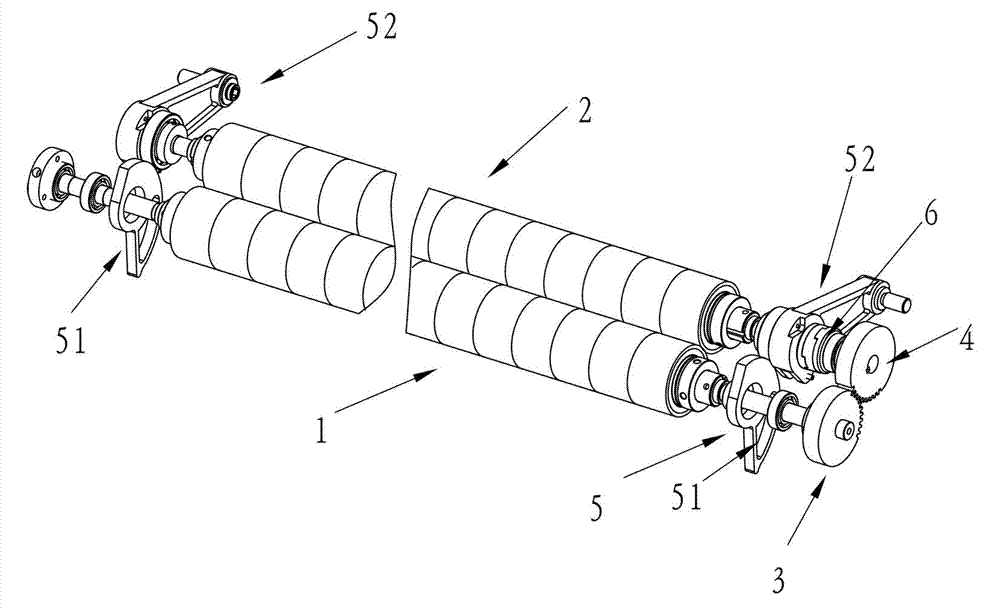
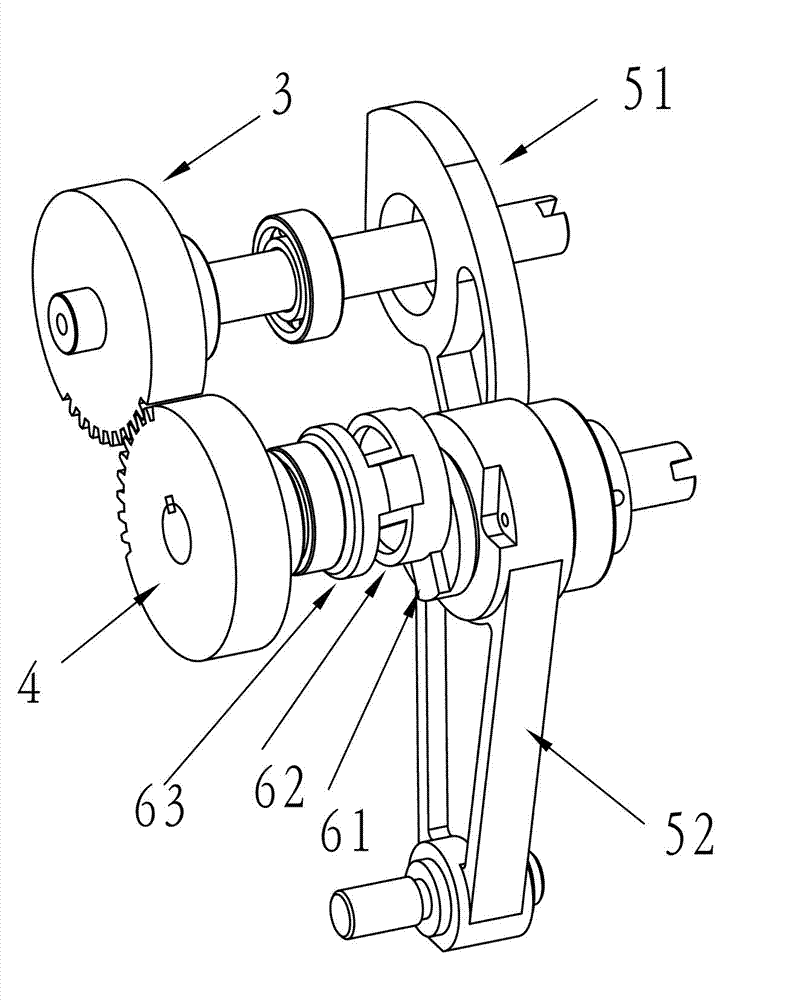
[0018] see figure 1 and Figure 4 . The driving gear 3 and the driven gear 4 of this specific embodiment mesh and rotate to drive the driving wheel 1 and the driven wheel 2 to rotate. The cam device 5 includes a fan-shaped cam 51 and a bearing 52 with a one-way self-locking function, and the cam 51 is installed on the driving wheel. On the shaft of 1, the rolling bearing 52 is installed on the shaft of the driven wheel 2, both of which are located at one end of the roller, and the outer circumference of the bearing 52 has an arc-shaped protrusion. below the joint. The cam 51 is self-locking in one direction and can only rotate counterclockwise relative to the driving wheel 1, and will be stuck when rotating clockwise. Therefore, when the driving wheel 1 rotates clockwise, the cam 51 rotates counterclockwise relative to each other, and the driving wheel 1 and the cam 51 can move with each other, so that the cam 51 can be locked by the arc-shaped protrusion on the bearing, so...


PUM


Abstract

The invention discloses a roller device of a flat knitting machine. The roller device comprises a cam device, a coupler device and a tension spring device, wherein the cam device comprises a cam and a bearing; the coupler device is mounted between the bearing and a driven gear; and the tension spring device is provided with a steel wire rope which is fixed on the bearing of the cam device. The roller device of the flat knitting machine has the advantages that a roller can be timely reset accurately after being opened thoroughly, and the position of a gear connected with the roller cannot be changed even if the position of the roller is changed, and the purpose of smoothly weaving is achieved.

Description

technical field [0001] The invention belongs to the technical field of knitting machines, in particular to a roller device of a flat knitting machine. Background technique [0002] The roller is a component used to pull the knitted fabric, and its function is to pull down the knitted fabric knitted by the needle bed. Because the roller has a certain distance from the needle plate, the roller cannot pull the fabric just woven. Therefore, a lifter is set between the roller and the needle plate, and the braided fabric on the needle plate is pulled to a position where the roller can be pulled by utilizing the lifter to rise. But in the lifting process of the lifting plate, the roller must be fully opened, so as to avoid collision with the lifting plate. However, in the prior art, the opening of the rollers may not be complete, resulting in a collision between the lifter and the rollers, which affects the service life of both. Another problem is: when the roller is opened, the...

Claims


Application Information

Patent Timeline
Patent Type & Authority Applications(China)
IPC IPC(8): D04B15/90
Inventor 孙平范
Owner NINGBO CIXING
Why Eureka
Try Eureka