
Casting die

A mold and movable template technology, applied in the field of manual casting molds, can solve the problems of easy deflection of copper terminals, inability to place copper terminals in place at one time, and reduce production qualification rate of pole terminals, so as to improve production qualification rate and production efficiency Effect

Inactive Publication Date: 2011-06-01
ZHAOQING LEOCH BATTERY TECH
View PDF4 Cites 9 Cited by
  • Summary
  • Abstract
  • Description
  • Claims
  • Application Information

AI Technical Summary

Problems solved by technology

Because this placement method cannot accurately place the copper terminal in place at one time, and the placed copper terminal is easy to deflect, this not only reduces the production efficiency of the pole terminal, but also reduces the production qualification rate of the pole terminal

Method used


Image

  • Casting die
  • Casting die
  • Casting die

Examples


Embodiment Construction

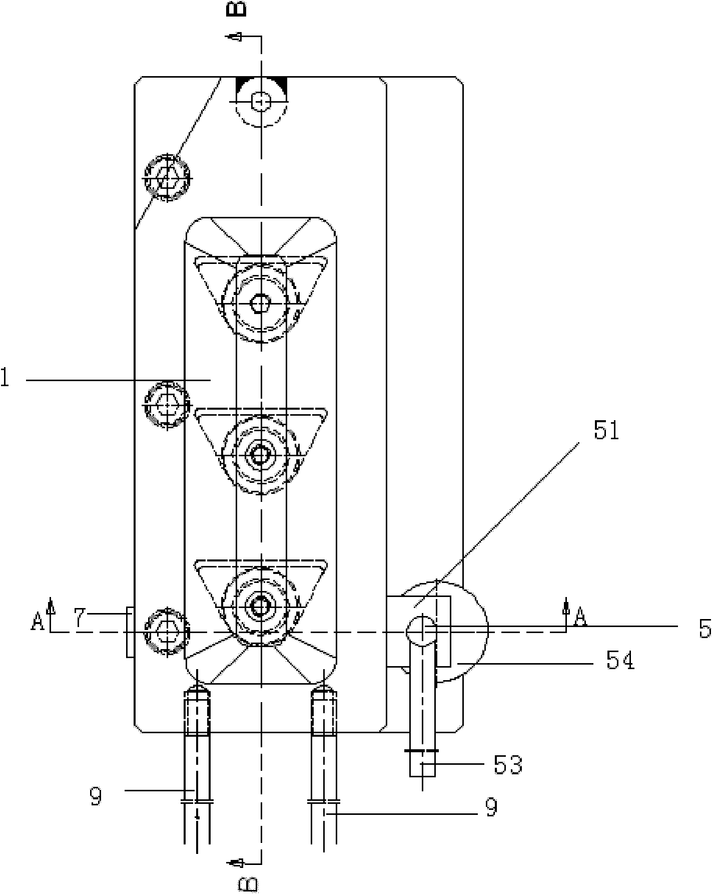
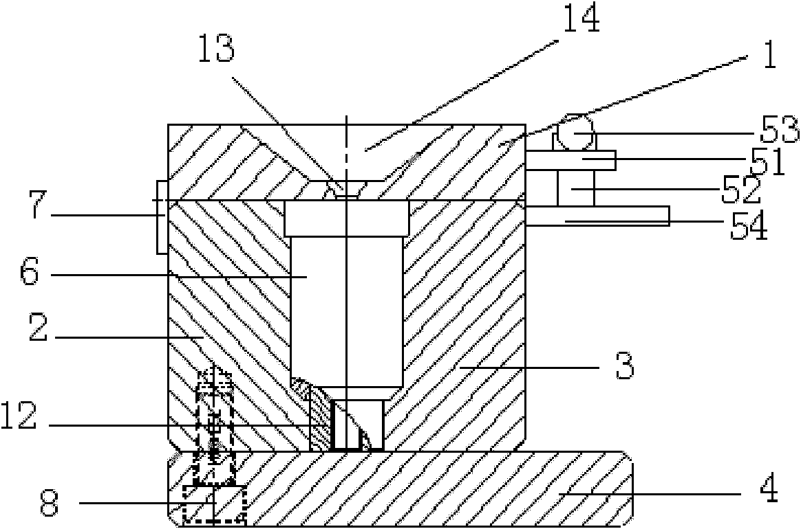
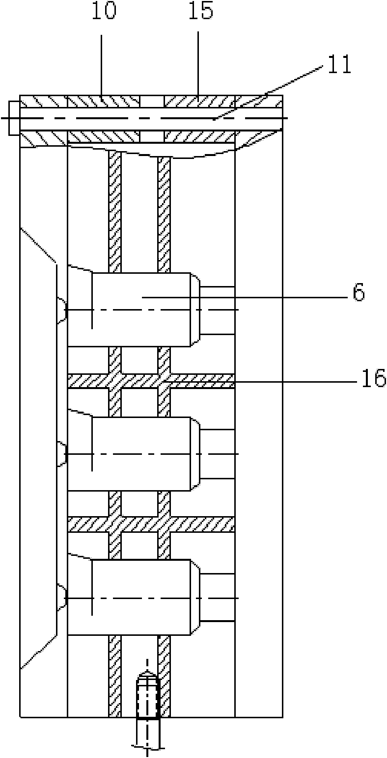
[0018] The pole terminal casting mold provided by the present invention includes a movable template, a fixed template fixed on the bottom plate, and a movable sprue plate located on the two templates when the movable template and the fixed template are molded together, and the movable template and the fixed template are symmetrical. When the mold is closed, the lower end of the product cavity formed by the cooperation of the movable module and the fixed module communicates with the bottom plate, that is, the lower end of the product cavity is in direct contact with the bottom plate, so that the lower end of the product directly leans against the bottom plate. On the bottom plate, even if the copper terminal of the pole terminal is directly against the bottom plate, when closing the mold, the copper terminal can be placed at the lower end of the cavity on the fixed template first, and one end of the copper terminal is against the bottom plate, and then Close the movable template...


PUM


Abstract

The invention provides a casting die, comprising a moving template, a fixed template fixed on a base plate, and a movable sprue plate, wherein when the moving template and the fixed template are closed, the movable sprue plate is positioned on the two templates; the moving template and the fixed template are respectively provided with a cavity, and when the moving template and the fixed template are closed, the cavities on the moving template and the fixed plate are matched to form a product cavity, the lower end of which is in direct contact with the base plate; and in the moving template and fixed template closing process, a copper terminal of a polar post terminal is firstly placed to the lower end of the cavity of the fixed template, the lower end of the copper terminal is directly supported against the base plate, and then the moving template is closed to fix the copper terminal to the lower end of the product cavity. Therefore, when the die provided by the invention is used for closing the moving template and the fixed template , the copper terminal can be accurately and vertically fixed at the lower end of the product cavity in one step so that the product cavity is unnecessary to form through closing the moving template and the fixed template, then the copper terminal is placed from the upper end of the product cavity and is repeatedly adjusted so that the copper terminal is fixed at the lower end of the product cavity, and thus, the production yield of the polar post terminals and the production efficiency are improved at the same time.

Description

technical field [0001] The invention relates to a casting mold, in particular to a manual casting mold for manufacturing battery pole terminals. Background technique [0002] The pole terminal is one of the components of the battery. It is a product formed by first putting the copper terminal into the designed casting mold, and then casting lead water into it to cool down. Because of the simple structure of the product, it is more convenient and practical to use hand-casting molds, so it is widely used. In the existing casting mold, when the mold is closed, the left module and the right module are often first combined to form a product cavity, and then the copper terminal forming the pole terminal is placed from the upper end of the formed product cavity. Because this placement method cannot accurately place the copper terminal in place at one time, and the placed copper terminal is easily deflected, this not only reduces the production efficiency of the pole terminal, but ...

Claims


Application Information

Patent Timeline
IPC IPC(8): B22D19/00H01M2/30
CPCY02E60/12Y02E60/10
Inventor 彭小勐熊正林胡天春
Owner ZHAOQING LEOCH BATTERY TECH
Learn More