
A speed control device for an engine

A technology of speed control device and engine, which is applied in the direction of engine control, machine/engine, mechanical equipment, etc., can solve the problems of a large number of parts of the speed governor, a large number of precision machining parts, and a large movement gap, and achieves a small number of parts and eliminates the Effects of delayed response and less movement gap

Active Publication Date: 2015-10-28
FUJIAN EVERSTRONG LEGA POWER EQUIP CO LTD
View PDF4 Cites 0 Cited by
  • Summary
  • Abstract
  • Description
  • Claims
  • Application Information

AI Technical Summary

Problems solved by technology

[0005] 3. The number of parts of the governor is large, the movement gap is large, and the response is sluggish;
[0006] 4. There are many special parts and precision machining parts, and the cost is high

Method used


Image

  • A speed control device for an engine
  • A speed control device for an engine
  • A speed control device for an engine

Examples


Embodiment Construction

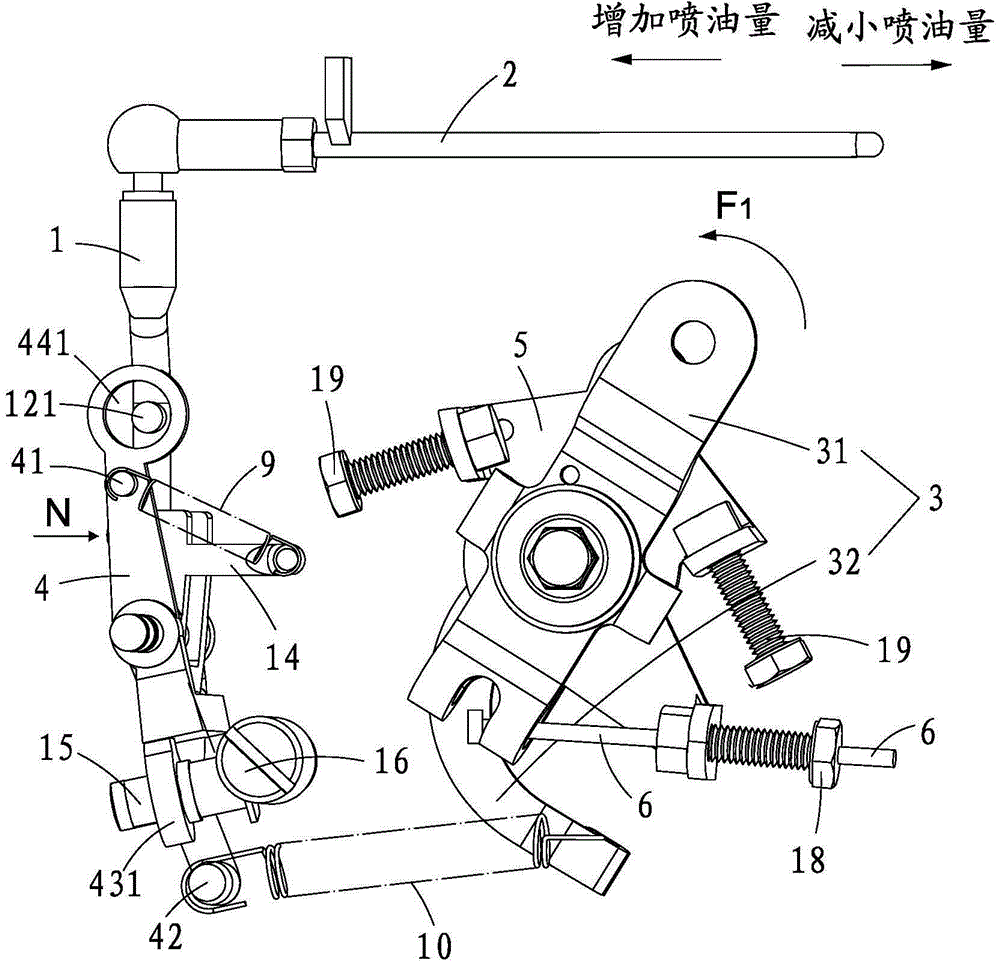
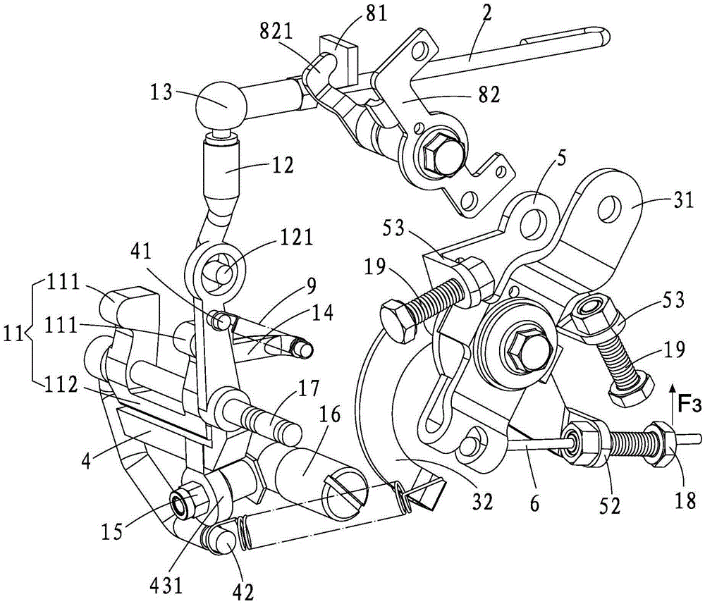
[0029] see Figure 1-2 , a speed control device for an engine, including a shift fork 1, a pull rod 2, a speed setting part 3, a speed control lever 4, a fixed frame 5, a flexible shaft 6, a return unit 7 and a stop Unit 8; the shift fork 1 is movably connected to the speed regulating lever 4, the speed setting part 3 is movably connected to the fixed frame 5, and the speed setting part 3 has a rocker arm 31 and a crank arm 32; The fixed frame 5 is fixedly connected with the engine (not shown).

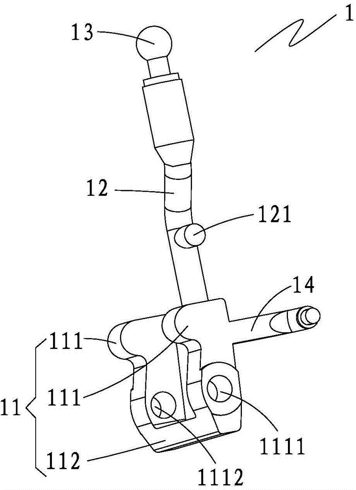
[0030] see again Figure 2-3 , the shift fork 1 includes a support frame 11 , a bending rod 12 , a ball head 13 and an adjustment component 14 . The support frame 11 includes a pair of tongues 111 and a horizontal member 112 connected to the bottoms of the two tongues 111; column 121 , and the ball head 13 is located at the top of the bending rod 12 . The ball head 13 is hinged to the pull rod 2 ; the adjustment component 14 is arranged at the rear upper part of the tongue 111 on ...


PUM


Abstract

The invention provides an engine speed regulating device which comprises a shifting fork, a pull rod, a rotating speed setting part, a speed regulating lever and a fixing frame, wherein the shifting fork is movably connected with the speed regulating lever; the shifting fork is provided with a ball head and an adjusting part; the ball head is hinged with the pull rod; the rotating speed setting part is movably connected with the fixing frame; the rotating speed setting part is provided with a rocker arm and a crank arm; the speed regulating lever comprises a first connecting part and a second connecting part; the first connecting part is connected with the adjusting part through a correction spring; the second connecting part is connected with the crank arm through a speed regulating spring; and the fixing frame is fixedly connected with the engine. The engine speed regulating device has full-range speed regulating and two-pole speed regulating functions, simple structure, fewer parts and small movement clearance, and the phenomenon of response lag of the speed regulating device can be eliminated; and due to multiple stamping parts, die castings and standard parts, the engine speed regulating device is convenient for mass production.

Description

【Technical field】 [0001] The invention relates to a speed governor, in particular to a speed regulating device of an engine. 【Background technique】 [0002] The existing speed regulating device of the engine is a centrifugal mechanical speed regulating device, which drives the shaft of the governor to rotate through gears, etc., and the governor is provided with a speed regulating fly block and a sliding sleeve. After the speed is set, under the action of centrifugal force, the flying block pushes the sliding sleeve to act on the speed control lever, and makes the rack of the fuel injection pump move to the side to reduce the fuel volume. Side movement, so as to realize the automatic adjustment of the fuel injection quantity of the engine. Yet the speed regulating device of existing engine has following shortcoming: [0003] 1. It is impossible to realize the functions of full speed regulation and bipolar speed regulation at the same time; [0004] 2. The functions of enr...

Claims


Application Information

Patent Timeline
Patent Type & Authority Patents(China)
IPC IPC(8): F02D1/04
Inventor 吕培源
Owner FUJIAN EVERSTRONG LEGA POWER EQUIP CO LTD
Learn More