Self-locking device of gears of speed changer

A technology of self-locking device and transmission, applied in transmission control, components with teeth, belt/chain/gear, etc., can solve the problems of complex manufacturing process and unreliable positioning, and achieve simple manufacturing process, reliable positioning, Guaranteed cleaning effect

Active Publication Date: 2012-11-14
GREAT WALL MOTOR CO LTD
View PDF8 Cites 2 Cited by
  • Summary
  • Abstract
  • Description
  • Claims
  • Application Information

AI Technical Summary

Problems solved by technology

After the self-locking ball enters the positioning groove, it is easy to overcome the friction force generated by the spring extrusion and break away from the positioning groove. The positioning is not reliable, and it is often necessary to process multiple holes corresponding to the positioning groove on the transmission housing to accommodate the spring. The manufacturing process is more complicated

Method used


Image

  • Self-locking device of gears of speed changer
  • Self-locking device of gears of speed changer
  • Self-locking device of gears of speed changer

Examples


Embodiment

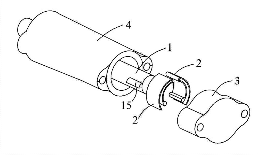
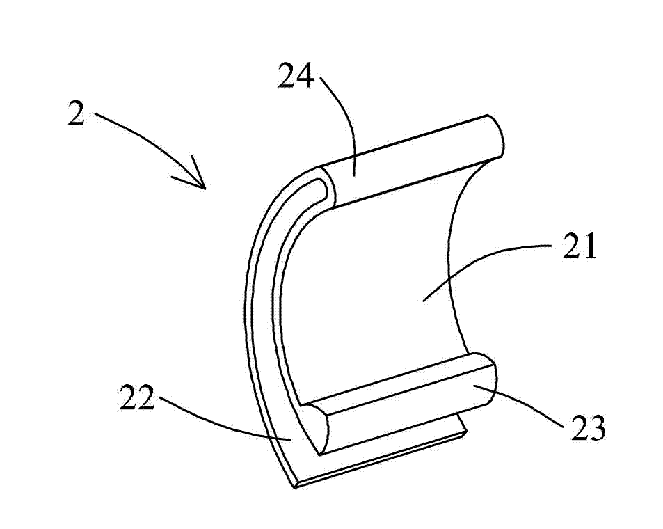
[0022] The present invention is a transmission gear self-locking device, the structure is as follows: Figure 1 to Figure 3 As shown, it includes a shift shaft 1 arranged on the transmission housing. The shift shaft 1 can slide axially between different shift positions. When it slides to the corresponding gear position, it can rotate around itself The axis of the shaft rotates, and the corresponding shift fork shaft is moved during the rotation to complete the shifting action. Two protruding self-locking blocks 15 are symmetrically arranged on both sides of the outer cylindrical surface of the shift shaft 1 , and two reeds 2 cooperating with the self-locking blocks 15 are correspondingly arranged on the transmission case.

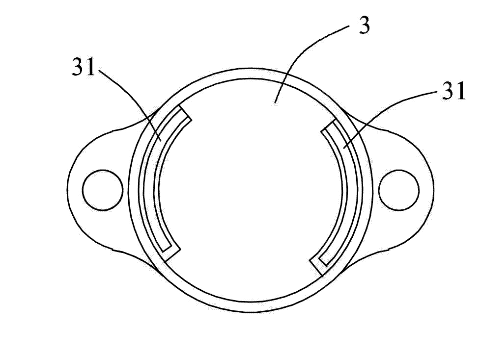
[0023] A connecting seat 3 is fixedly connected to the transmission housing, and the connecting seat 3 is used to fix the reed 2 on the housing. It has two symmetrical half-ring-shaped slots 31 inside. The stop shaft 1 is arranged coaxially, and is used fo...


PUM


Abstract

The invention discloses a self-locking device of gears of a speed changer. The self-locking device comprises a gear shifting shaft which can be axially slidably arranged on a speed changer casing and can rotate along the self axis so as to perform gear shifting on the speed changer. The self-locking device further comprises a reed fixedly arranged on the speed changer casing. The reed is provided with a compressible section which is partially separated from the speed changer casing and can be compressed in the radial direction of the gear shifting shaft, and a blocking part is fixedly arranged on the compressible section. A protruded self-locking block is arranged on the outer cylindrical surface of the gear shifting shaft, is located on one side of the blocking part, presses and crosses the blocking part when the gear shifting shaft rotates to perform gear shifting, and reaches the other side of the blocking part. By enabling the self-locking block positioned on the gear shifting shaft to be matched with the blocking part positioned on the reed, when the self-locking block slides to the other side of the blocking part, self locking of the gear shifting shaft is achieved under the elastic effect of the blocking part, and the self-locking device is reliable to position and simple in manufacture process. The self-locking device is suitable for various speed changers, and self locking of the gears of the speed changers is achieved.

Description

technical field [0001] The invention relates to a gear position locking device of a transmission, which is used for self-locking the gear position of a transmission, in particular to a gear position self-locking device of a transmission. Background technique [0002] The existing gear position self-locking device of the transmission uses a spring to push the self-locking ball into the positioning groove provided on the shift shaft. After the shift shaft slides axially to the corresponding shift position, it rotates around its own axis for shifting. block. During its rotation, the self-locking device slides into the corresponding positioning groove to realize the self-locking of the shift shaft in this gear. After the self-locking ball enters the positioning groove, it is easy to overcome the friction force generated by the spring extrusion and break away from the positioning groove. The positioning is not reliable, and it is often necessary to process multiple holes corres...

Claims


Application Information

Patent Timeline
Patent Type & Authority Applications(China)
IPC IPC(8): F16H63/34
Inventor 张晓鹏杨光高海龙顾明晖刘磊
Owner GREAT WALL MOTOR CO LTD
Why Eureka
Try Eureka