
Electronic device

一种电子装置、容置槽的技术,应用在测量装置、电话通信、电气元件等方向,能够解决组成构件多、设计及制造复杂、增添成本等问题,达到降低制造成本、结构简单、节省使用空间的效果

Active Publication Date: 2012-11-14
WISTRON CORP
View PDF4 Cites 2 Cited by
  • Summary
  • Abstract
  • Description
  • Claims
  • Application Information

AI Technical Summary

Problems solved by technology

[0003] However, this method of engaging the hook and the slot is inconvenient during assembly or disassembly, and during the assembly process, it is necessary to push the battery module to make the hook engage with the slot of the locking member. , therefore, it is easy to cause the hook to break
In addition, the locking member and the biasing spring of the locking mechanism will occupy the space inside the housing, so that the space inside the housing cannot be fully utilized
Furthermore, the locking mechanism has many components, and the design and manufacture are relatively complicated, which easily increases the manufacturing cost.

Method used


Image

  • Electronic device
  • Electronic device
  • Electronic device

Examples


Embodiment Construction

[0053] The foregoing and other technical contents, features and effects of the present invention will be clearly presented in the following detailed description of an embodiment with reference to the accompanying drawings. Through the description of the specific implementation, the technical means and effects of the present invention to achieve the intended purpose can be understood more deeply and specifically. However, the attached drawings are only for reference and description, and are not used to limit the present invention. .

[0054] Before the present invention is described in detail, it should be noted that in the following description, similar elements are denoted by the same reference numerals.

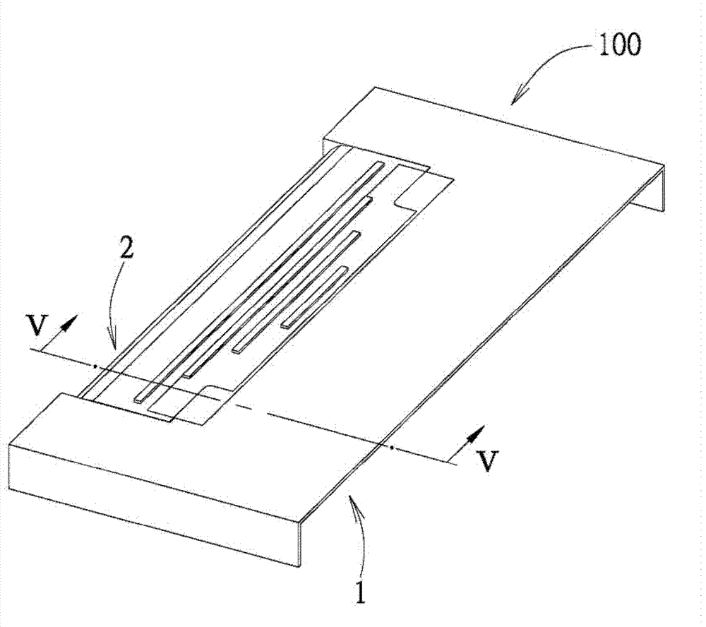
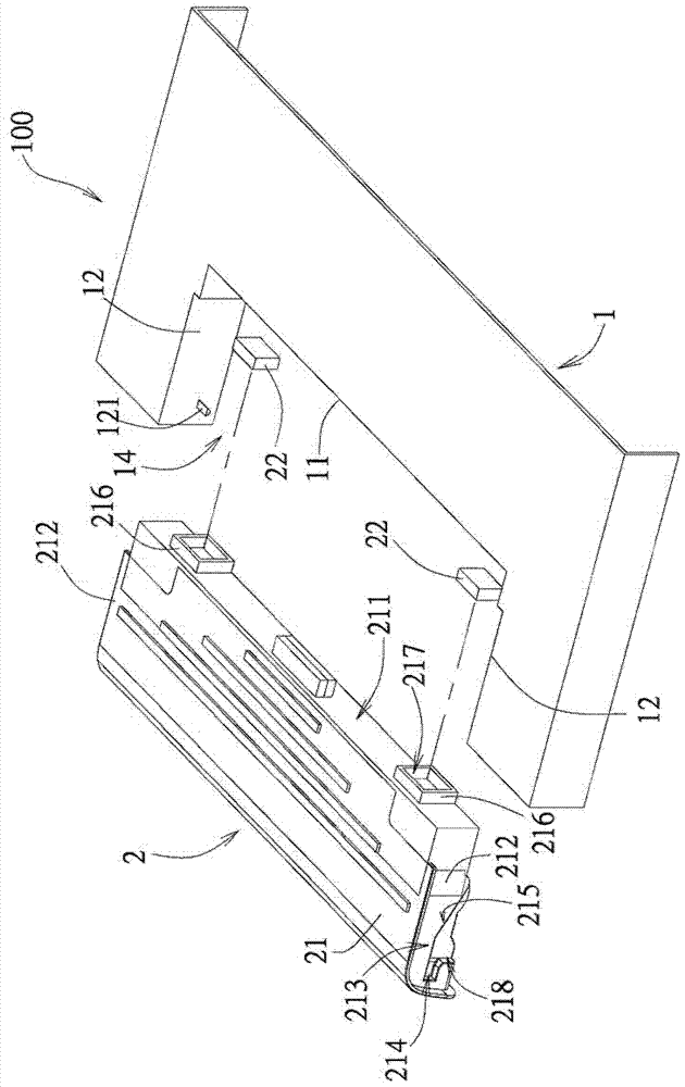
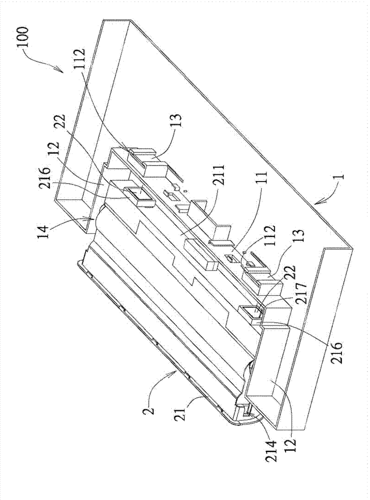
[0055] Such as figure 1 and figure 2 Shown is an embodiment of the electronic device of the present invention, the electronic device 100 includes a case 1 and a battery module 2 . In this embodiment, the electronic device 100 is illustrated by taking a notebook computer...


PUM


Abstract

The present invention discloses an electronic device including a casing and a battery module. The casing includes a connecting wall, two inner side walls connected to opposite ends of the connecting wall and having pillars protruding therefrom, and a first magnetic member disposed at the connecting wall. The connecting wall and the inner side walls cooperatively define a receiving space. The battery module is arranged in the receiving space, and includes a housing and a second magnetic member, wherein, the housing includes a first side wall to abut against the connecting wall and two second side walls that are connected respectively to the opposite ends of the first side wall, the second magnetic member is disposed at the first side wall and has a magnetic attraction force with the first magnetic member, each of the second sidewalls is formed with a guiding groove, the guiding groove includes a positioning portion that extends horizontally for engagement with the pillar, and an inclining portion that spatially communicates the positioning portion with an ambient space for guiding sliding movement of the pillar into the positioning portion.

Description

technical field [0001] The invention relates to an electronic device, in particular to a locking mechanism of the electronic device. Background technique [0002] At present, the locking mechanism of the battery module of a notebook computer is usually provided with a locking piece inside the casing, and a locking groove is formed on the locking piece, and the locking piece is biased by a biasing spring so that the locking piece is kept in a locked position. The battery module is protruded with a hook for locking in the slot. To assemble and fix the battery module on the housing, first align the hook of the battery module with the slot and apply force to push the battery module so that it locks into place. The hook is engaged in the slot, so that the battery module is locked on the casing. When the battery module is to be disassembled, the battery module can be removed from the housing by pushing the locking member to slide to the release position relative to the housing so...

Claims


Application Information

Patent Timeline
Patent Type & Authority Applications(China)
IPC IPC(8): G06F1/26G06F1/18
CPCG06F1/1658H04M1/0202H04M1/0262
Inventor 林政弘汪志毅林文泰
Owner WISTRON CORP
Features
  • Generate Ideas
  • Intellectual Property
  • Life Sciences
  • Materials
  • Tech Scout
  • Unparalleled Data Quality
  • Higher Quality Content
  • 60% Fewer Hallucinations
Learn More