Electromagnetic assembly structure of alternating current contactor and alternating current contactor

A technology of AC contactor and assembly structure, which is applied in the direction of electromagnetic relay, detailed information of electromagnetic relay, circuit, etc. It can solve the problems of shortening the service life of the coil, occupying a large space, and complicated wiring, so as to reduce the risk of short circuit, facilitate wiring, The effect of improving assembly efficiency

Active Publication Date: 2012-11-14
ZHEJIANG CHINT ELECTRIC CO LTD
View PDF5 Cites 4 Cited by
  • Summary
  • Abstract
  • Description
  • Claims
  • Application Information

AI Technical Summary

Problems solved by technology

[0002] In the field of power distribution, it is often necessary to use contactors for frequent power breaking/closing. For electromagnetically controlled contactors, continuous power supply is required when they are closed to keep the coil working and pull the contacts of the contactor. The contactor The current required at start-up is significantly greater than the current required to maintain the coil. If the coil at start-up is used to keep the contactor closed, it will cause obvious waste of electric energy. Therefore, the existing contactors generally use double windings with auxiliary switches to save energy. Electromagnetic structure, that is, use a large coil when pulling in, and switch to a small coil to maintain the pulling state after pulling in
In order to realize double-winding switching, multiple wires nee

Method used


Image

  • Electromagnetic assembly structure of alternating current contactor and alternating current contactor
  • Electromagnetic assembly structure of alternating current contactor and alternating current contactor
  • Electromagnetic assembly structure of alternating current contactor and alternating current contactor

Examples


Example Embodiment

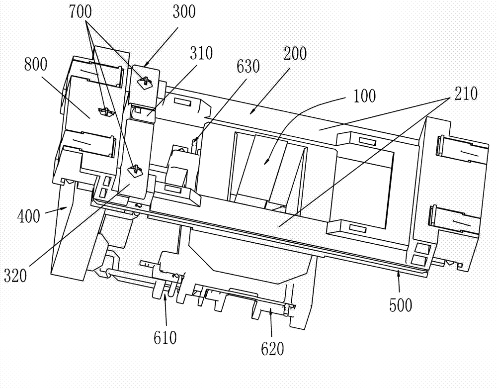
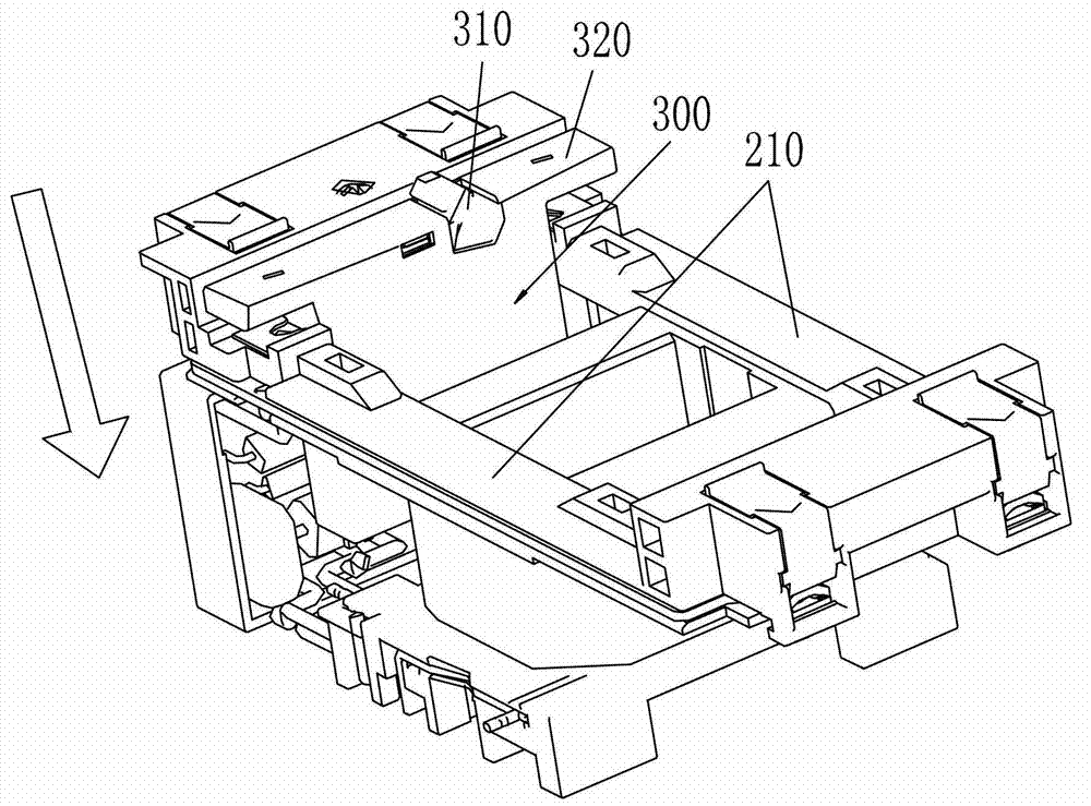
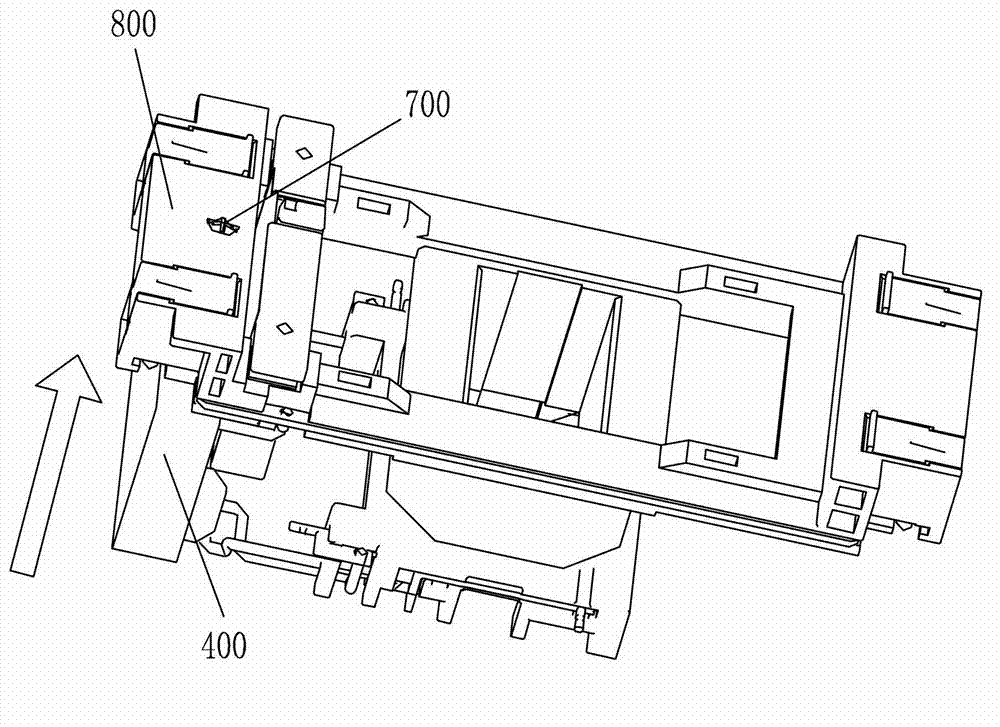
[0024] The invention discloses an AC contactor, which includes an electromagnetic assembly structure of the AC contactor. The electromagnetic assembly structure of the AC contactor includes a control module of the AC contactor, a double coil winding and a coil skeleton for fixing the double coil winding . The double-coil winding includes a starting winding and a holding winding. There is a common end between the starting winding and the holding winding. The lower end of the winding lug is provided with a winding lug; one end of the power lug is coupled to the control module, and the other end is connected to the power input end; one end of the winding lug is coupled to the control module, and the other end is connected to the double coil winding.

[0025] Because the present invention couples the power supply input terminal to the control module through the power supply lug, and couples the double-coil winding through the winding lug, the wiring is convenient and the assembly ...


PUM


Abstract

The invention relates to an electromagnetic assembly structure of an alternating current contactor and the alternating current contactor. The electromagnetic assembly structure of the alternating current contactor comprises a control module of the alternating current contactor, a double-coil winding and a coil framework for fixing the double-coil winding, wherein the coil framework is provided with a power terminal lug at the upper end where the double-coil winding attracts an armature of the alternating current contactor; the lower end opposite to the upper end of the coil framework is provided with a winding terminal lug; one end of the power terminal lug is coupled to the control module, and the other end is connected to a power input end; one end of the winding terminal lug is coupled to the control module, and the other end of the winding terminal lug is connected to the double-coil winding. As the power input end is coupled to the control module through the power terminal lug, the wiring is convenient and the assembly efficiency is improved through the double-coil winding coupled by the winding terminal lug; meanwhile, the power terminal lug and the winding terminal lug are arranged on the upper end and the lower end of the coil framework, so that the structure is compact, and the input end and the output end are separated; and the risk of a short circuit caused by the wrong wiring is reduced.

Description

technical field [0001] The invention relates to the field of power distribution, and more specifically, relates to an electromagnetic assembly structure of an AC contactor and the AC contactor. Background technique [0002] In the field of power distribution, it is often necessary to use contactors for frequent power breaking / closing. For electromagnetically controlled contactors, continuous power supply is required when they are closed to keep the coil working and pull the contacts of the contactor. The contactor The current required at start-up is significantly greater than the current required to maintain the coil. If the coil at start-up is used to keep the contactor closed, it will cause obvious waste of electric energy. Therefore, the existing contactors generally use double windings with auxiliary switches to save energy. Electromagnetic structure, that is, a large coil is used when pulling in, and it is switched to a small coil to maintain the pulling state after pul...

Claims


Application Information

Patent Timeline
IPC IPC(8): H01H49/00H01H50/44
Inventor 吴兴雷杨军朱映平肖体锋
Owner ZHEJIANG CHINT ELECTRIC CO LTD
Why Eureka
Try Eureka