A shaped heater for an aerosol generating system

A heater and aerosol technology, used in water heaters, fluid heaters, pharmaceutical devices, etc., can solve problems such as inefficient heating of tobacco materials, achieve efficient heating treatment, reduce the possibility of damage, reduce temperature and The effect of electricity

Active Publication Date: 2012-11-14
PHILIP MORRIS PROD SA
View PDF7 Cites 17 Cited by
  • Summary
  • Abstract
  • Description
  • Claims
  • Application Information

AI Technical Summary

Problems solved by technology

One disadvantage of this proposed smoking article is that the heating element is not in direct contact with the tobacco material, and therefore the resistive heating element only heats the tob

Method used


Image

  • A shaped heater for an aerosol generating system
  • A shaped heater for an aerosol generating system
  • A shaped heater for an aerosol generating system

Examples


Embodiment Construction

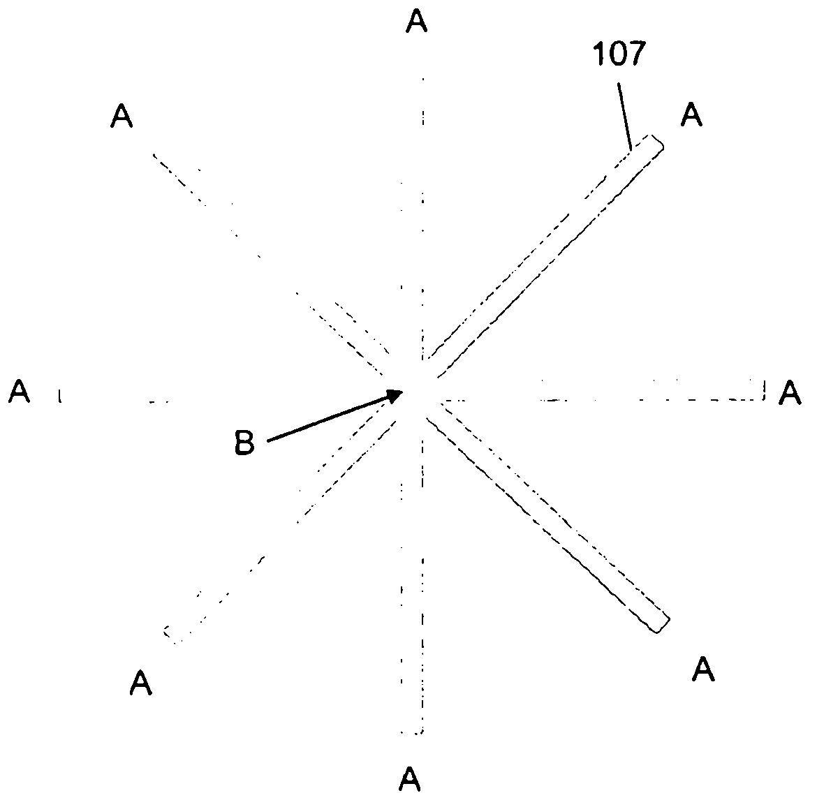
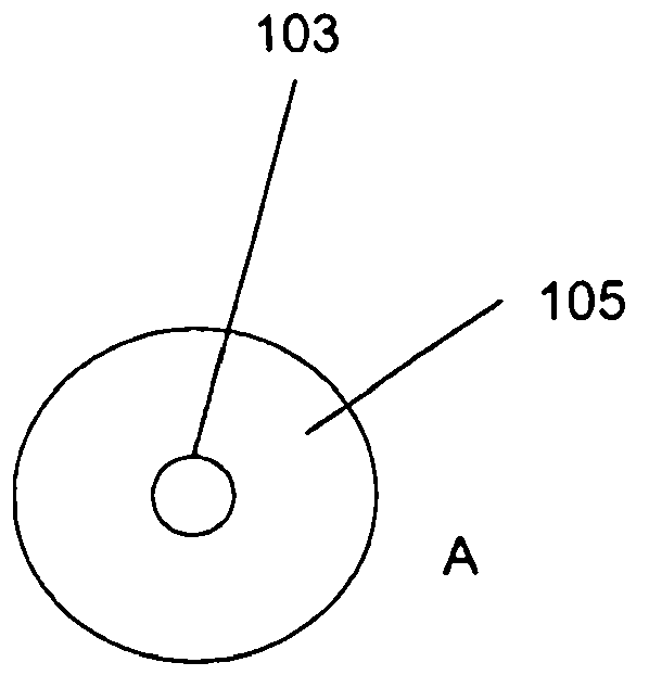
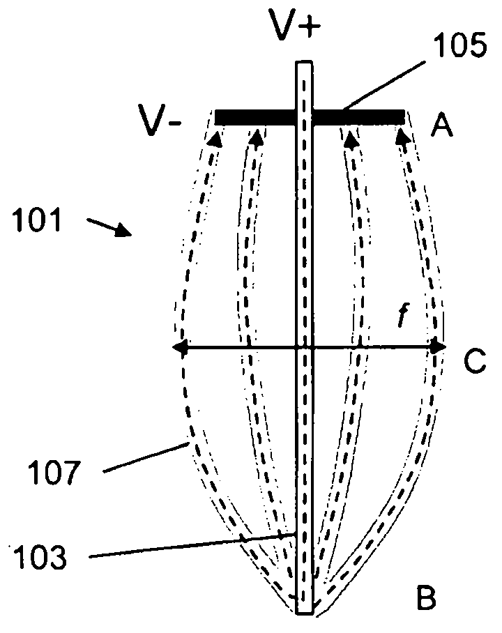
[0064] Figures 1 to 5 , 7 and 8 show a first embodiment of the heater of the present invention. Specific reference figure 1 , 2 and 3, the heater 101 comprises a conductive pin in the form of a common pin 103 , an annular ring 105 and a plurality of heating elements 107 . The assembled heater 101 has a ring end portion A, a heating end portion B and a middle portion C. As shown in FIG. figure 1 The heating element 107 is shown after it has been formed by flat stamping a sheet of suitable material before final assembly. figure 2 The ring portion including annular ring 105 and common pin 103 is shown prior to final assembly. The annular ring 105 may be an electrically insulating material, and the annular ring 105 acts as a support to hold image 3 Location of heating elements of the shape shown. The annular ring 105 can also hold the common pin 103 in a substantially central position on the ring. In the embodiment of centralized control (common control) to the heating e...


PUM


Abstract

There is provided a heater (101) for heating an aerosol-forming substrate. The heater comprises a plurality of elongate heating elements (107) arranged in an elongate array. The elongate array has a support end with a first dimension, a heating end with a second dimension and a middle portion with a third dimension. The array is arranged to heat the substrate to form an aerosol. The third dimension is greater than the first dimension and greater than the second dimension. There is also provided an electrically heated aerosol generating system including such a heater.

Description

technical field [0001] The present invention relates to a heater for heating an aerosol-forming substrate. Preferably, but not exclusively, the invention relates to an electric heater for heating an aerosol-forming substrate and to a heater for an electrically heated aerosol-generating system. A particular application of the invention is an internal heater for an electrically heated smoking system for heating an aerosol-forming substrate having a cavity. Background technique [0002] EP-A-0358020 discloses a smoking article comprising a cigarette having a resistive heating element for heating tobacco material in the cigarette. The cigarette has an electrical connection plug for connection to a reusable handheld controller. The handheld controller includes a battery and a current control circuit that controls the supply of power to a resistive heating element in the cigarette. One disadvantage of this proposed smoking article is that the heating element is not in direct co...

Claims


Application Information

Patent Timeline
IPC IPC(8): A24F47/00A24F40/20A24F40/46A24F40/70
CPCA24F47/008F24H1/0018A24F40/46A24F40/70A24F40/20A24B15/167A61M15/06A24F40/10H05B3/0019H05B3/46H05B2203/017A61M2205/8206
Inventor O·格雷姆F·费尔南多C·T·希金斯
Owner PHILIP MORRIS PROD SA
Why Eureka
Try Eureka