Touch sense using time domain reflectometry

A technology of touch position and time, applied in the input/output process of data processing, instruments, calculations, etc., can solve the problems of expensive, complex touch sensor matrix supporting electronic equipment manufacturing and so on

Inactive Publication Date: 2012-11-14
MICROCHIP TECH INC
View PDF8 Cites 16 Cited by
  • Summary
  • Abstract
  • Description
  • Claims
  • Application Information

AI Technical Summary

Problems solved by technology

Furthermore, the fabrication of the touch sensor matrix in the panel and the supporting electronics to it can be complex and expensive

Method used


Image

  • Touch sense using time domain reflectometry
  • Touch sense using time domain reflectometry
  • Touch sense using time domain reflectometry

Examples


Embodiment Construction

[0030] Referring now to the drawings, details of exemplary embodiments are schematically illustrated. Like elements in the drawings will be represented by like numbers, and like elements will be represented by like numbers with different lowercase letter suffixes.

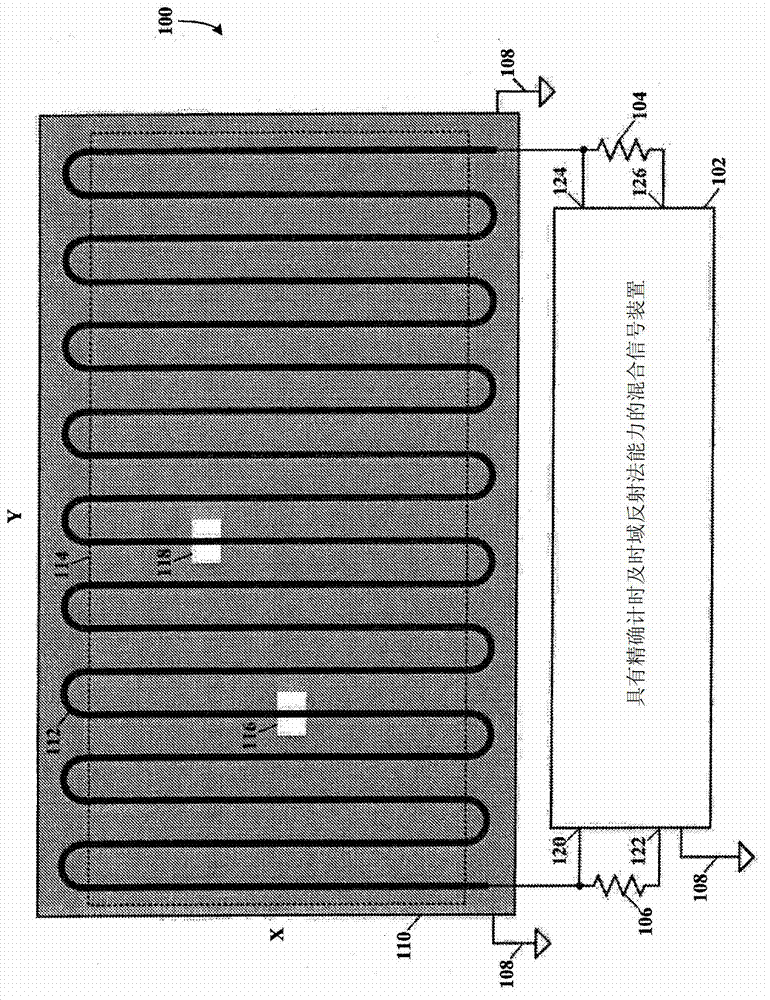
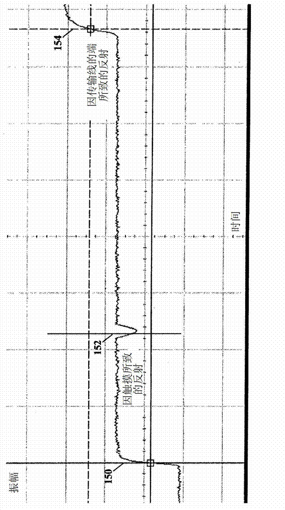
[0031] Time domain reflectometry (TDR) operates on principles similar to radar. A pulse of energy is transmitted down a conductive path (eg, a transmission line) with constant impedance. When the pulse reaches the unterminated end of the conductive path, or there is an impedance change along the conductive path, part or all of the energy pulse is reflected back to its source. When two metal conductors are placed in close proximity together, they form a transmission line with a characteristic impedance determined by the spacing of the metal conductors and the insulating dielectric therebetween. If the transmission line is terminated with its characteristic impedance, there will be no reflected pulse at the beginni...


PUM


Abstract

A touch panel or screen has a serpentine transmission line fabricated on a substrate, e.g., printed circuit board, LCD, plasma or LED screen, etc., and has a constant impedance. A touch to the touch panel will cause a change of impedance of the transmission line at the location of the touch. Time domain reflectometry (TDR) is used for determining the location of the change of impedance of the transmission line by accurately measuring the return pulse time at the source of the initial pulse, and then converting the return pulse time to X-Y coordinates of the touch panel or screen.

Description

[0001] Related Application Cross Reference [0002] This application claims to be filed April 30, 2010 by James E. Bartling, Padmaraja Yedamale and Jerry Hanauer and titled Co-owned U.S. Provisional Patent Application No. 61 / 329,650 for "Touch Sense Using Time Domain Reflectometry"; and which is hereby incorporated by reference for all purposes incorporated into this article. technical field [0003] The present invention relates to touch sensing panels and touch sensing panel screens, and more particularly, to sensing touched locations on touch sensing panels and touch sensing screens by using time domain reflectometry (TDR). Background technique [0004] Touch-sensing panels and touch-sensing screens are used in a myriad of applications for interfacing users with consumer appliances, commercial and industrial control panels, and the like. Multiple touch sensors (eg, capacitive, inductive, resistive) arranged in a matrix can each be individually actuated by placing an ob...

Claims


Application Information

Patent Timeline
Patent Type & Authority Applications(China)
IPC IPC(8): G06F3/041
CPCG06F3/041G06F3/044G06F3/04166G06F3/0416
Inventor 詹姆斯·S·巴特林帕德玛拉佳·耶达玛拉力杰里·哈诺尔
Owner MICROCHIP TECH INC
Why Eureka
Try Eureka