
Portable fracture external fixing rack

An external fixator, portable technology, applied in medical science, surgery, etc., can solve the problems of incapable of meeting war, field emergency use, many components, inconvenient to carry, etc., to avoid fixation failure, high fixation strength, easy to use and wear. Effect

Active Publication Date: 2014-07-16
刘建 +1
View PDF14 Cites 4 Cited by
  • Summary
  • Abstract
  • Description
  • Claims
  • Application Information

AI Technical Summary

Problems solved by technology

[0002] There are many kinds of fixation frames used in the treatment of fractures, but they all have the disadvantages of complex structures and many components. It is inconvenient for patients with fractures to carry after installation and use, and cannot meet the needs of war and field first aid.

Method used


Image

  • Portable fracture external fixing rack
  • Portable fracture external fixing rack
  • Portable fracture external fixing rack

Examples


Embodiment 1

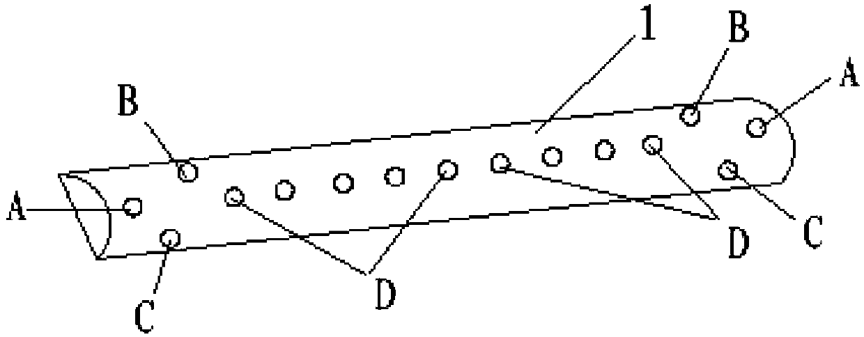
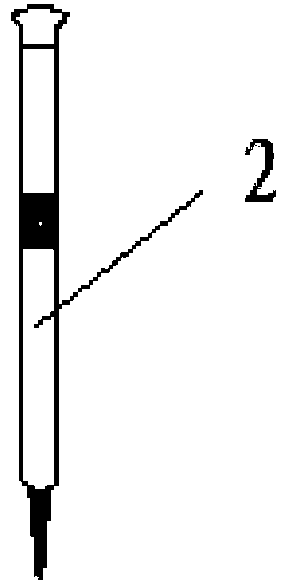
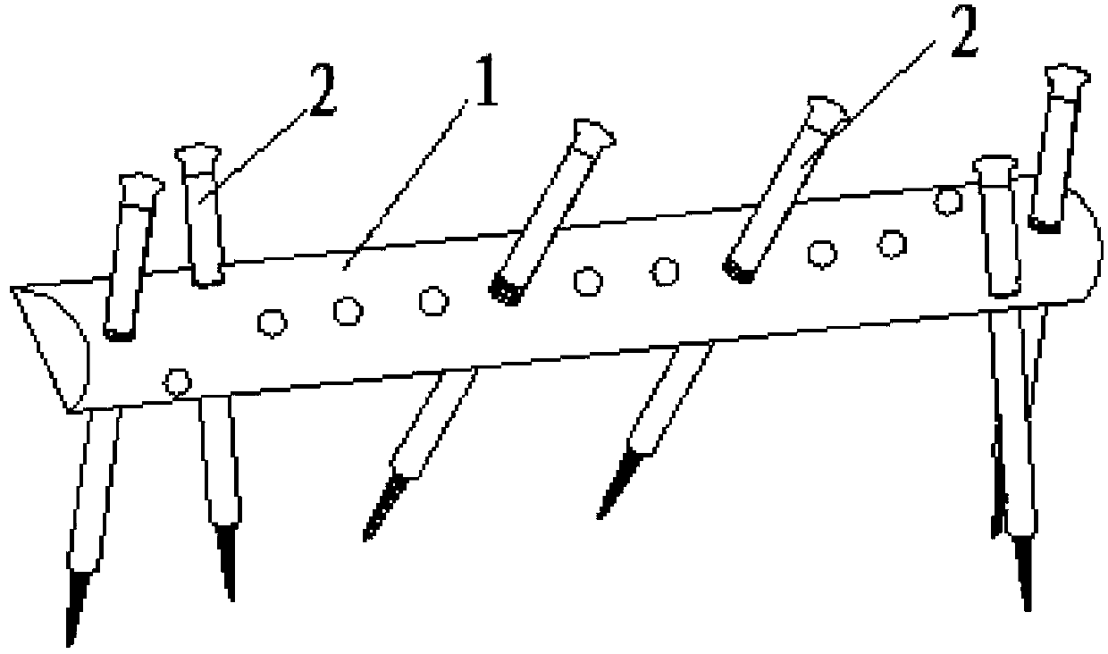
[0020] Such as Figure 1 to Figure 3 As shown, a portable fracture external fixator of the present invention includes a main frame rod 1 made of carbon fiber material and a plurality of fixation pins 2 . Carbon fiber material has high rigidity, light weight, and is transparent to X-rays. Main frame bar 1 is long 20cm, wide 2cm, high 1.5cm, and cross section is semi-ellipse. The middle section of the rod body of the main frame rod 1 is provided with nine vertically threaded through holes D evenly arranged. Above, the distance between two adjacent two of the nine vertical threaded through holes D is 1.5 cm, and the distance between the outermost two vertical threaded through holes D and the outer edge of the corresponding end of the main frame rod 1 is 4 cm. Both ends of the rod body of the main frame rod 1 are provided with symmetrical first oblique threaded through hole A, second oblique threaded through hole B and third oblique threaded through hole C, the distance between ...

Embodiment 2

[0023] The difference between this embodiment and embodiment 1 is: 1. Use the first main frame bar 1-1 and the second main frame bar 1-2 of the same size, and the first main frame bar 1-1 and the second main frame bar 1-2 When the frame rods 1-2 are arranged symmetrically up and down, the corresponding threaded through holes on the first main frame rod 1-1 and the second main frame rod 1-2 are connected to each other so as to install the same fixed pin 2. 2. To add two The friction between the main frame rods, the plane surfaces of the first main frame rod 1-1 and the second main frame rod 1-2 are rough surfaces. The parameters of the first main frame rod 1 - 1 , the second main frame rod 1 - 2 and the fixed pin 2 are the same as those in the first embodiment.

[0024] Such as Figure 4 and Figure 5 As shown, when this embodiment is in use, according to the needs of the fixed strength and / or fixed length, the first main frame bar 1-1 and the second main frame bar 1-2 can be...


PUM


Abstract

The invention discloses a portable fracture external fixing rack which comprises one or two main rack rods and a plurality of fixing needles. The cross section of each main rack rod is semi-elliptical; the middle of a rod body of each main rack rod is provided with a plurality of vertical threaded through holes extending in the directions perpendicular to the trend of the main rack rod; two ends of the rod body of each main rack rod are provided with a plurality of slant threaded through holes extending in the directions obliquely crossed with the main rack rod; the slant threaded through holes at two ends of each rod body are arranged symmetrically; the sizes of the vertical threaded through holes are identical to those of the slant threaded through holes; outer threads which are matched with the vertical threaded through holes or the slant threaded through holes are arranged in the middle of each fixing needle; one end of each fixing needle is a conical self-tapping and self-drilling needle head; and the fixing needles are fittingly mounted on the main rack rods in a threaded manner. The portable fracture external fixing rack is high in bone external fixation reliability, and is simple in structure, few in components, simple in installation and convenient to carry after being installed.

Description

technical field [0001] The invention belongs to the technical field of medical equipment, and in particular relates to a portable fracture external fixator. Background technique [0002] There are many kinds of fixation frames used in the treatment of fractures, but they all have complex structures and many components. After installation and use by patients with fractures, they are inconvenient to carry, and cannot meet the needs of war and field first aid. Contents of the invention [0003] The purpose of the present invention is to provide a portable fracture external fixator, which has high reliability of external bone fixation, simple structure, few components, simple installation and easy portability after installation. [0004] A technical solution adopted by the present invention is a portable fracture external fixator, which is characterized in that it includes a main frame rod, the cross section of the main frame rod is semi-elliptical, and the middle section of t...

Claims


Application Information

Patent Timeline
Patent Type & Authority Patents(China)
IPC IPC(8): A61B17/60
Inventor 刘建高嘉锴孟国林段春光程建岗袁志杨鹏
Owner 刘建
Learn More